A Hamstring Recovery Bionic System
Abstract
The hamstring muscles are a muscle group crucial to daily function, especially for movements like walking, running, and jumping. That’s why hamstring strains, or any disruption to the muscle-tendon structures of the hamstring grouping, are particularly debilitating.
We propose a bionic system that effectively promotes hamstring strain healing in the early stages of more severe cases of our target pathology while operating efficiently. The report details the design process and technical reasoning that informed our design. Pathology and bionic simulation, transmission design calculations, physical architecture, and control framework are all discussed.
I. Background
A. Pathology Description
A hamstring strain, aptly named, is an injury to the hamstring muscles. Qualitatively, it is commonly characterized by a sudden, sharp pain in the back of the thigh. In consequence, increased exertion activities such as running, or extending the hip and bending the knee strongly, become painful and difficult to control.
A strain is the generalized term used to describe an injury to the greater hamstring musculature. This can be further specified as a strain (micro tear), tear, or rupture that can occur in the muscle belly or musculotendinous region, or a combination of these injury sites and severities.
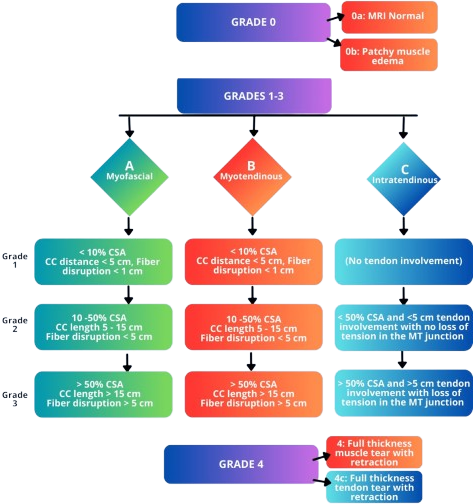
Although non-standardized and quite convoluted, the severity of the strain is often diagnosed using a grading system 1. Most grading schemes follow an I-III or 0-4 level structure. More advanced grading structures separate the finer details of hamstring injury, combining severity grading and anatomic site classification across the musculotendinous region.
Secondary Pathologies 2: Tendon rupture (especially at insertion) can cause retraction or bone fragment avulsion, in the case that the tension in the tendon forcefully rips off a portion of bone from the tendon insertion site.
Anatomy
The hamstrings anatomically comprise a group of muscles and their associated tendons that satisfy the following definitions 345:
- Originates from the ischial tuberosity.
- Inserted over the knee joint, in the tibia or fibula.
- Innervated by the tibial branch of the sciatic nerve.
- Participates in knee flexion and hip extension.
![Reference: Gray's Anatomy (1918) [^15]](/assets/media/bionic-hamstring_media/hamstrings.png)
| Muscle | Origin | Insertion |
|---|---|---|
| Semitendinosus | Ischial tuberosity | Medial tibia |
| Semimembranosus | Ischial tuberosity | Medial tibial condyle |
| Biceps femoris (LH) | Ischial tuberosity | Fibular head (lat) |
| Biceps femoris (SH) | Linea aspera | Fibular head (lat) |
B. Mechanism of Injury
Hamstring strains are a highly recurring injury, particularly in athlete populations 67. Hamstring strains are reported to account for 12–16% of all injuries in athletes, with a reported re-injury rate of 22-34%.
One major risk factor for hamstring injuries is high-impact movements involving the legs, such as sprinting, jumping, and quick changes of direction, hence why this injury disproportionately affects athlete populations.
C. Prior Art
Rehabilitation strategies and protocols are in place to expedite and enhance the healing process 8. Conservative care is the standard for Grade I–II hamstring strains, typically involving rest, cryotherapy, partial immobilization, and pain control, followed by progressive stretching and strengthening as symptoms improve.
Beyond traditional methods of passive recovery and additional rehabilitative efforts, experimental treatments such as peptides may be introduced to promote healing factors. In severe cases such as complete hamstring tendon rupture, surgical intervention may be warranted 9. One paper, for instance, discusses proximal hamstring repair with all-suture anchors.
II. Biomechanical Modeling
In order to perform simulations on locomotive performance for normal gait and affected gait, as well as assess the impact of our proposed bionic solution, we must accurately represent our pathology computationally.
The entirety of our modeling workflow is run through the OpenSim API.
A. Model Selection
We use GaitModel2392 to represent our human musculoskeletal system, a complete top-down 23-DOF computer model 10. The models were created by Darryl Thelen (University of Wisconsin-Madison) and Ajay Seth, Frank C. Anderson, and Scott L. Delp (Stanford University). The models feature lower extremity joint definitions adopted from Delp et al. (1990), low back joint and anthropometry adopted from Anderson and Pandy (1999), and a planar knee model adopted from Yamaguchi and Zajac (1989). The Gait2392 model features 92 musculotendon actuators to represent 76 muscles in the lower extremities and torso.
Model Details:
- Muscles of interest in the model are listed as:
semimem_r,semiten_r,bifemsh_r(short head of biceps femoris),bifemlh_r(long head of biceps femoris). - We expect 10 degrees of freedom
- 16.64 Nm (average leg weight of 13 kg for a 70kg person, uninjured peak torque of 1.28 Nm/kg) of peak torque
- velocity of 60°/s
- Additional distributed mass of modeled exoskeleton cannot exceed 2.5 kg.
- This open source model conveniently comes with a motion file. The original 75.82kg model is scaled down to match the dimensions of the test subject tied to this motion file.
B. Pathology Characterization
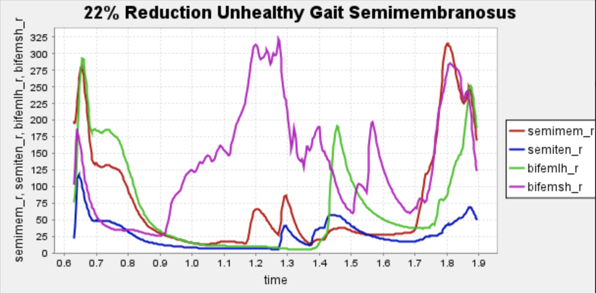
The pathology of a hamstring strain is mechanically characterized by a change in the force-length relationship in the affected muscle, resulting in a loss of force production potential in the larger ranges of motion of the muscle 6. Given the complexity of this relationship and the inability to shape unique force-length curves for the infinite varieties of hamstring strains, we simplified the pathology to its most notable and generalized performance reductions, specifically a decrease in the maximum isometric force of the hamstring muscles. During injury, typically, patients experience a range of 10% reduction to 22% peak torque reduction encompassing eccentric and concentric motion, so we will be evaluating the pathological gait at a 22% reduction in max isometric force of the muscles of interest, the larger end of this figure. This will model the most “generalized” case of hamstring strain immediately after injury.
To further simplify and sharpen the focus of our bionic design, we have honed in on the semimembranosus muscle as our specific hamstring muscle of choice.
C. Bionic System Modelling
Our modeling abstraction must conform to the OpenSim framework and its selection of objects. The bionic system is represented in OpenSim as a path actuator object, which applies a controllable tension along a path running parallel to the hamstring muscles. A force limit parameter, decided by the real-world motor it represents, is set on the path actuator to more realistically represent true motor performance. This representation and how it is used to inform our bionic design will be discussed in the bionic system design portion of the report.
D. Simulation Procedure
- Load GaitModel2392, and scale the model to the desired size to match the proportions of our motion file.
- Out of the scaled model, create 3 separate models (healthy normal gait, weakened semimembranosus gait, and weakened semimembranosus gait with a path actuator). All subsequent steps will be performed on all 3 models for comparison.
- We tested various path actuator representations with varying max forces potentials (400, 600, 700, 566 N) and landed on a 566N actuator as the optimal choice. It struck a balance of reducing activations enough while not being overkill and potentially adding more weight to the system with a beefier actuator.
- Perform inverse kinematics to derive joint angles from motion. Plot angle and moment for
semimem_r,semiten_r,bifemsh_r(short head of biceps femoris),bifemlh_r(long head of biceps femoris) for healthy gait. - Run Residual Reduction Algorithm (RRA) to improve the accuracy of CMC results.
- Run Computed Muscle Control (CMC) to obtain muscle activation information. We will use activation to measure system performance.
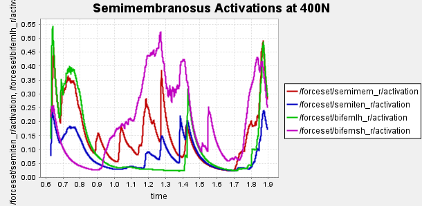
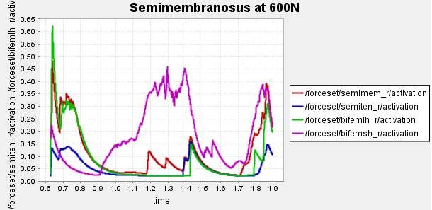
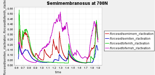
Figure 4: Activation of hamstring muscles during 1 cycle of a patient with a semimembranosus tear (unhealthy gait) with path actuator assistance (400N, 600N, 700N max force potential actuators). Normalized to [0,1]
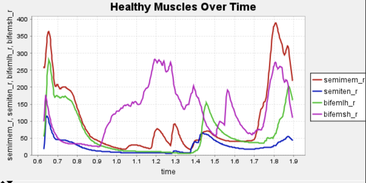
Here is our finalized representation of hamstring muscle activation across three cases (healthy gait, unhealthy gait, and unhealthy gait with bionic system). The reserve actuator usage and tracking error plots remain within acceptable limits, indicating that the model executed the motion without excessive reliance on non-physiological actuators. Accordingly, we consider the simulation results reliable for continued analysis. All supporting plots are included in the Appendix.
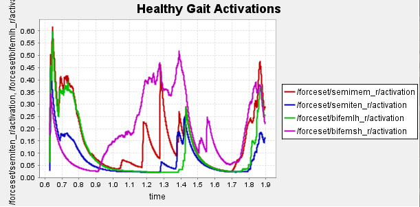
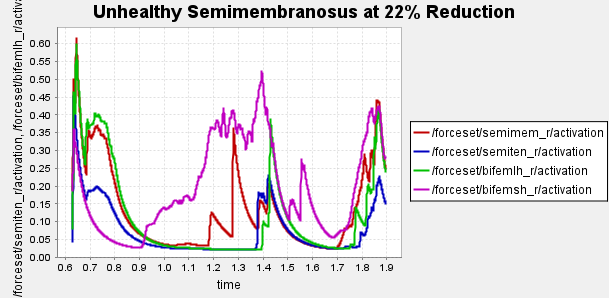
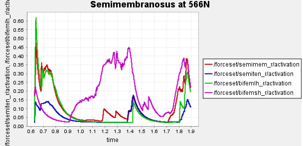
Figure 5: Activation data gathered from CMC of healthy, unhealthy, and unhealthy assisted gaits. Normalized to [0,1]
Data collected at this stage will inform our bionic system design, discussed in the next section.
III. Bionic System Design
The primary goal of our exo system is to minimize the activation of the affected muscle, promoting healing while maintaining comfort and metabolic efficiency. We proposed a set of design criteria/considerations to direct the design process.
Design Specifications:
- We will assume the weight of the bionic system should not exceed 2.5 kg.
- The system should accomplish the desired tasks while being optimized for energy efficiency, which secondarily reduces battery size (further decreasing weight and improving efficiency)
- Reduce the activation of the affected muscle, the semimembranosus, as much as possible.
- Minimize contact with soft tissue (for better control bandwidth)
- Strap doesn’t pressure veins due to muscle volume change (prevents tourniquet effect)
A. General Description
Our device is a powered knee skeleton designed to assist patients recovering from a hamstring tear. The exoskeleton is worn on one leg and spans from the mid-thigh to the shank, with soft straps around the thigh and calf and a small anchor near the ankle. A lightweight external frame follows the lateral contour of the leg and houses a brushless DC motor (Maxon EC-4pole 30, Ø30 mm, 200 W) mounted at the knee joint. The motor drives the knee through a 215:1 transmission, allowing it to generate biologically relevant flexion/extension torques while keeping the actuator compact.
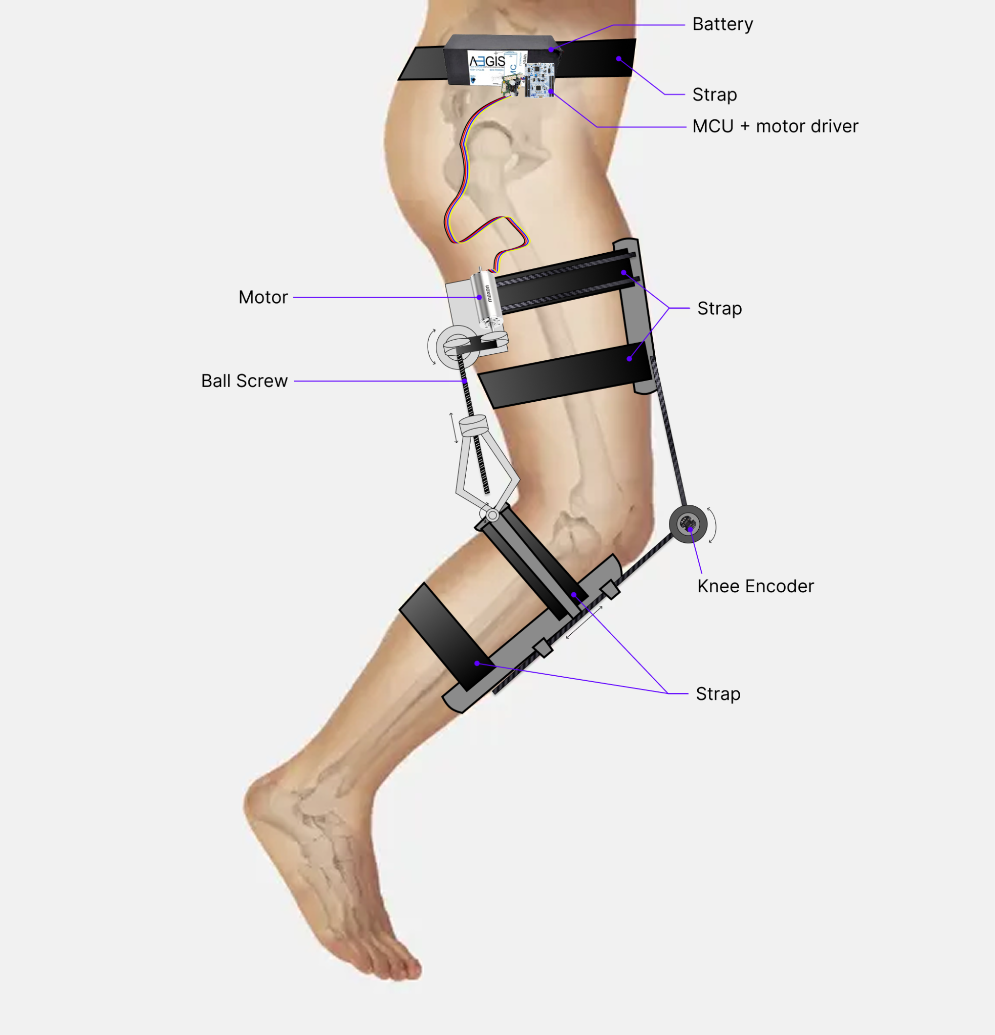
The system attaches to the body using adjustable straps at the thigh and calf that are connected to a simple kinematic linkage. When the knee bends, this linkage actively loosens the straps to accommodate the increased leg circumference, preventing a tourniquet effect and improving comfort and circulation. When the leg is extended, the straps automatically tighten again to provide a secure mechanical connection for torque transfer. In operation, the device supplies assistive knee torque during gait to reduce the load on the injured hamstring muscles while preserving natural joint motion and user comfort.
B. Optimization Problem
The most crucial area of our bionic system and the initial reason for the bionic’s existence is to reduce activation in the semimembranosus muscle.
How do we go about finding an optimal actuated system that reduces semimembranosus activation? We use the aforementioned path actuator, a simplified model representation of our active bionic mechanism, to take up slack. We increase the peak actuation (force) of the motor until reductions in activations of the injured muscle become negligibly different (but overall decreased), or else the motor selection tied to its peak actuation results in a motor and battery combination that could exceed our threshold of 2.5 kg.
The capability of our actuator is limited by its energy consumption, which has the secondary effect of adding weight via the battery. So not only will a more powerful motor add weight via a more bulky motor, it may add compounded weight via a bulky battery. Essentially, we need to push the performance capabilities of our desired system while toeing the line of our 5% bodyweight threshold for our complete bionic framework.
Based on the desired trajectory from the OpenSim modeling we picked an off-the-shelf motor, model its electrical/mechanical performance, check current and heat, discuss heat dissipation, and choose a battery with enough voltage such that the device can be used for the entire day, so that that the combined weight, along with an estimate of the bionic frame weight, hopefully so that our mass requirement is not exceeded. Then we will choose an optimal energy-minimizing transmission ratio and the materials/devices to achieve that transmission ratio.
C. Actuator Selection and Transmission Ratio Optimization
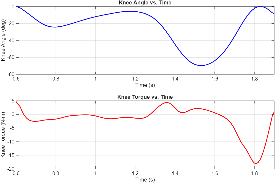
The healthy knee joint torque and angle over time for one step were exported to MATLAB. A 100-sample-per-second window was applied to smooth the results, and the resulting plots closely match the OpenSim plots. The segments with high angular acceleration and/or torque drive the motor specifications.
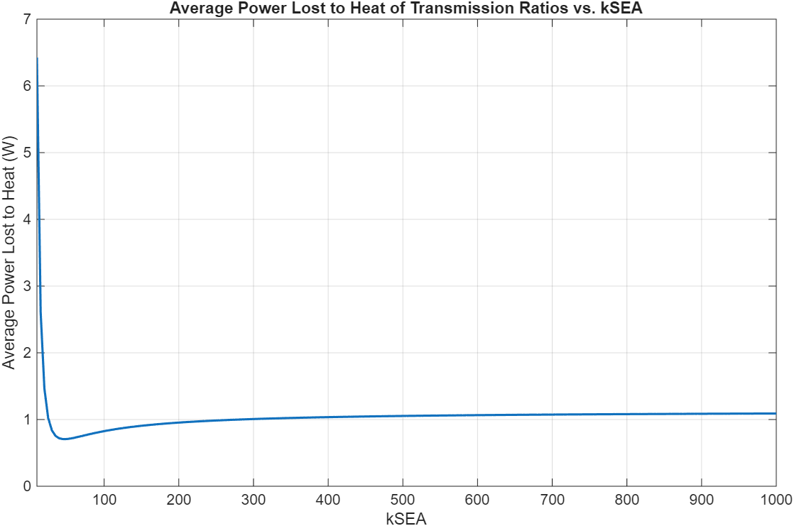
13 Maxon motors with various characteristics and geometries were compared. Energy lost to heat was the cost function used to select the optimal motor and transmission ratio combination. A 4-pole brushless motor from Maxon (Part number 305015) with a 215:1 transmission ratio was the best.
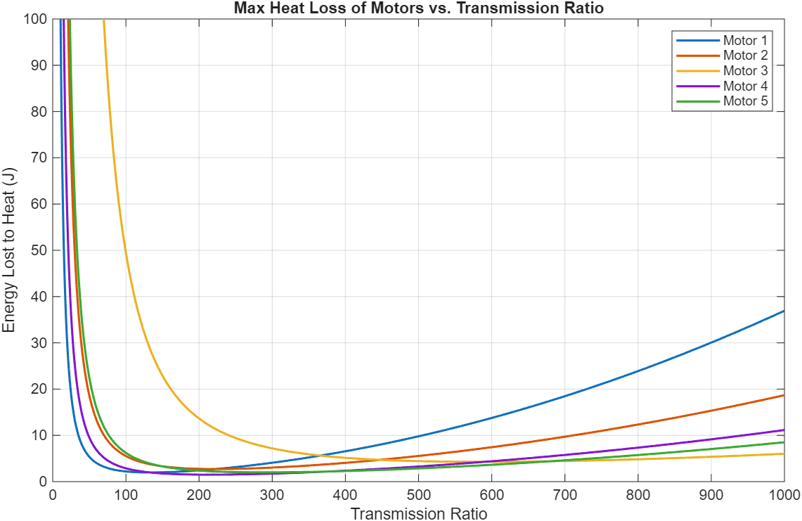
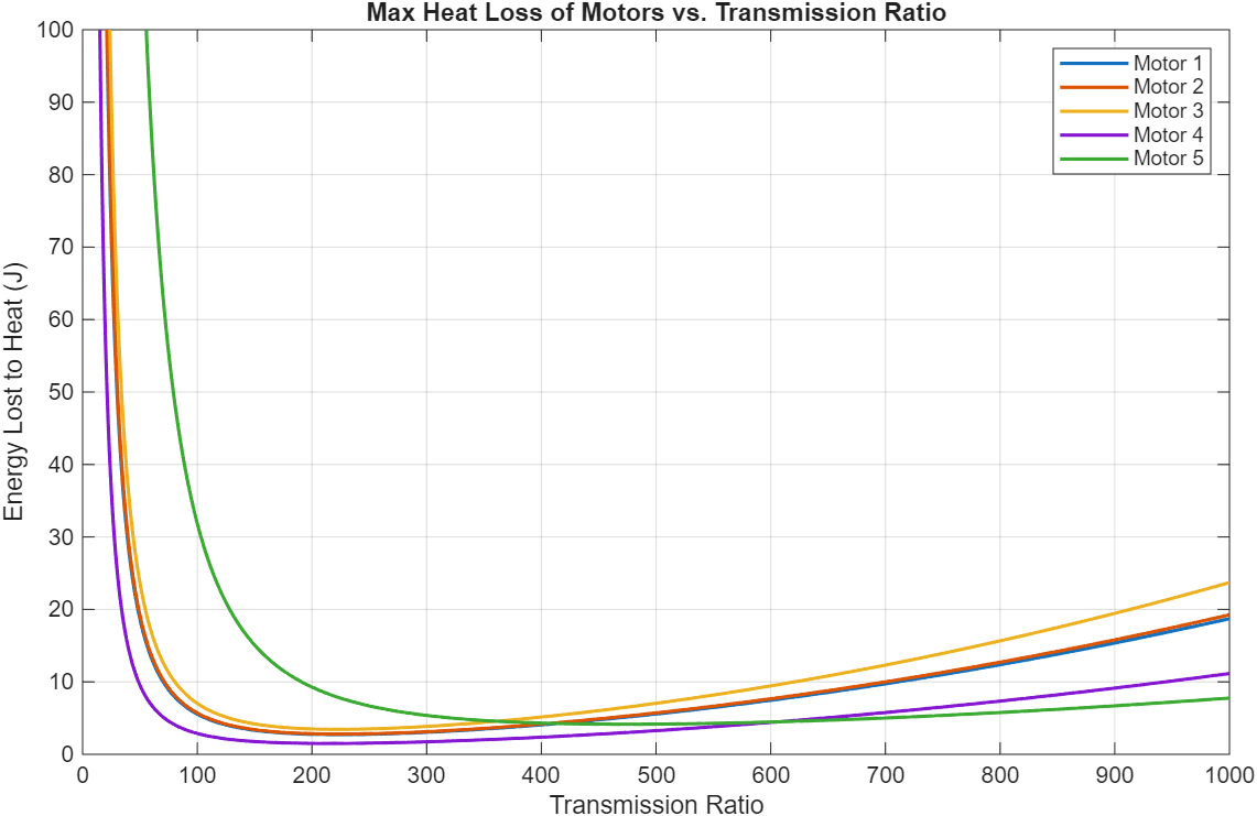
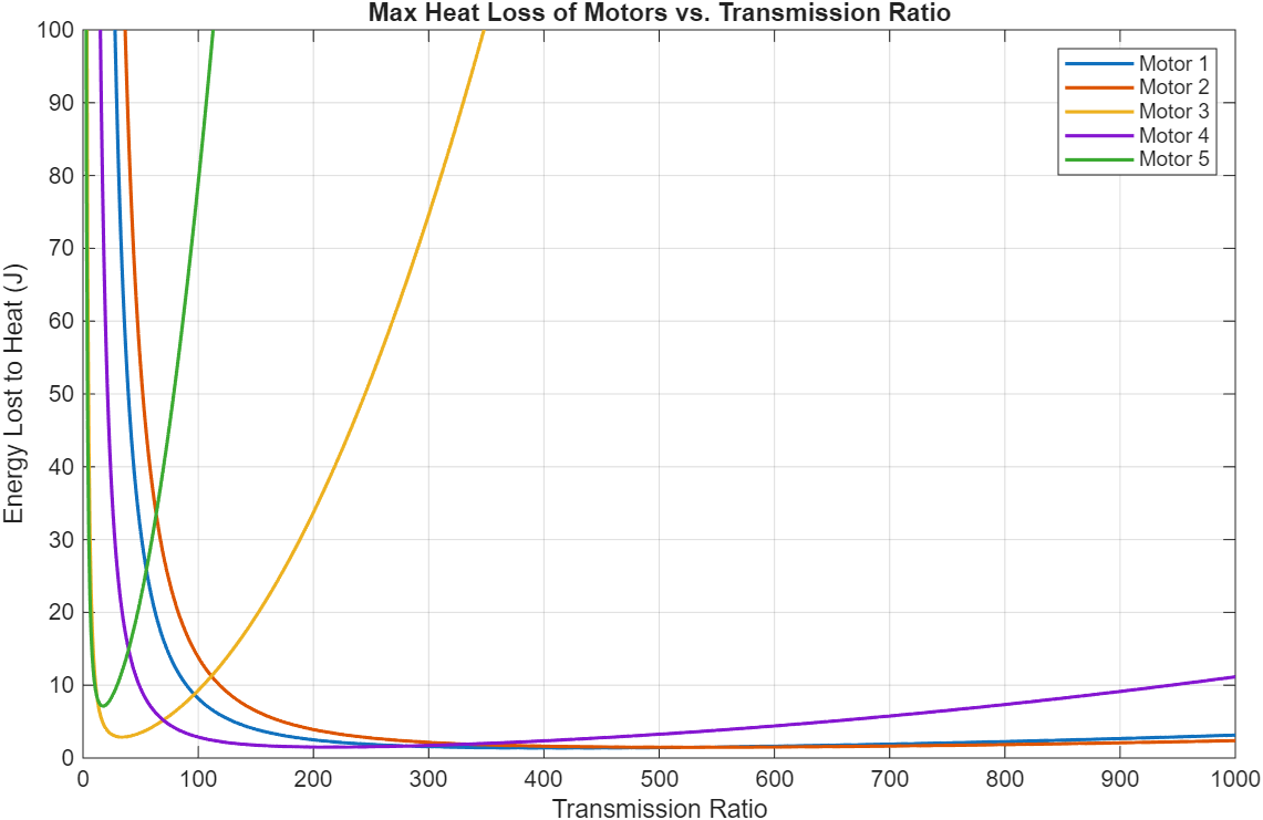
Figure 8: 3-staged comparison of 13 different motors and their energy dissipation to heat loss across different transmission ratios.
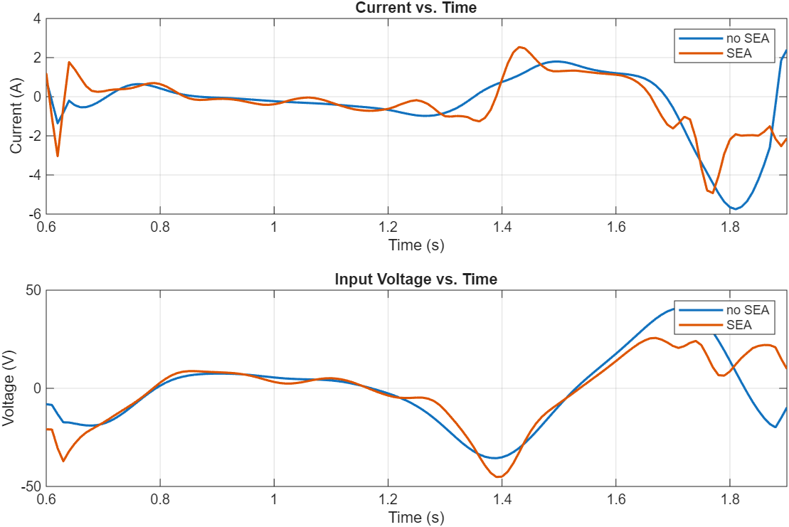
Plotting the current draw and input voltage for this motor and transmission ratio combination yields the following plot.
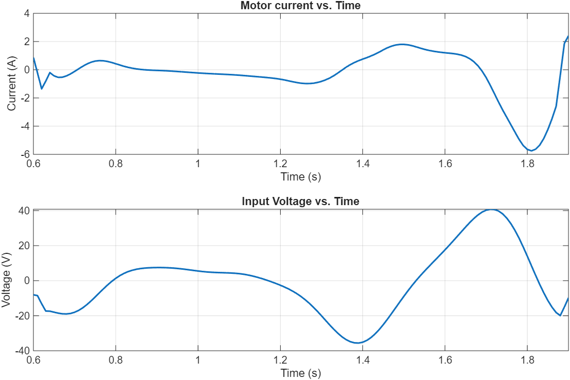
This combination results in about 1.47J of energy lost to heat. This does not sound like a lot, but since this occurs per step, the heat would build up quickly. To dissipate this heat, a finned motor housing can be used.
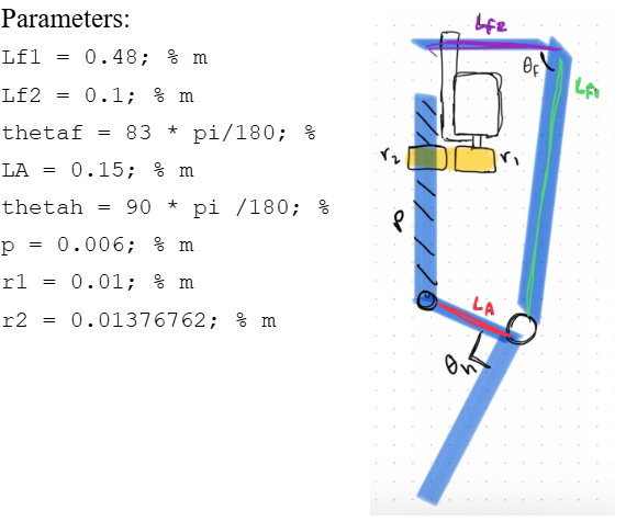
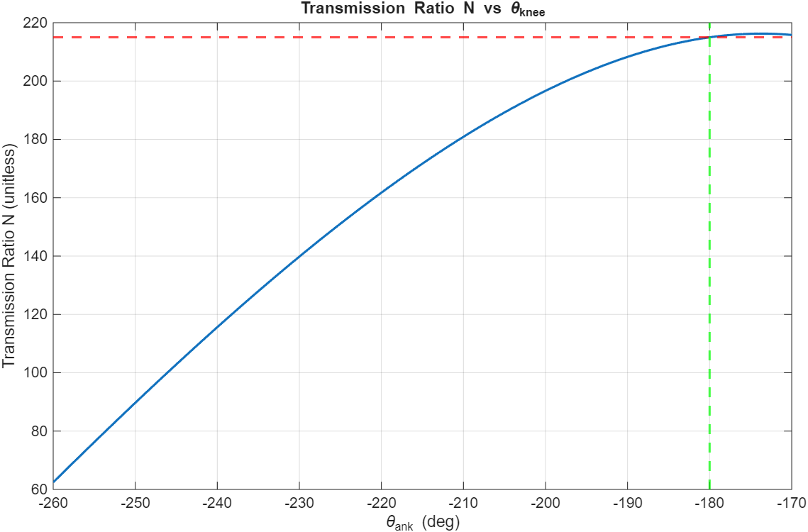
A rotary-to-linear transmission system was designed as the peak transmission ratio can be selected to be achieved at a certain joint angle. Since the peak torque of the knee is achieved at 0 degrees of knee flexion, the 215:1 transmission ratio should be the peak and achieved at the equivalent -180 degrees. It is not a worry that the knee will go past -180 degrees, as there will be a hard stop to prevent the knee from bending this way. Using the following parameters, a peak transmission ratio of 215:1 is achieved at 0 degrees of flexion as needed.
D. Series Elastic Actuation (SEA)
We evaluated the performance impact of integrating a series elastic actuator. It was concluded that the efficiency gains derived from SEA are negligible, making SEA an unnecessary inclusion in our bionic system.
E. Battery Selection
We estimated the required battery capacity based on the electrical energy per step.
From our simulations, the exoskeleton consumes 273.6 J per step. For 5,000 steps per day, this gives a total daily energy of:
\[E_{\text{day}} = 273.6~\text{J/step} \times 5{,}000~\text{steps} = 1{,}368{,}000~\text{J}\]Converting to watt-hours, $E_{\text{day}} = 1{,}368{,}000 / 3{,}600 \approx 380~\text{Wh}$. To include a safety margin for battery aging and modeling error (about 1.2–1.3×), we target a battery around 48 V, 10 Ah, which provides approximately 480 Wh. This corresponds well to the estimated daily energy use. For reference, we consider the Aegis 48V 10Ah Lithium Ion Battery Pack (NMC 48V Lithium Battery).
With a 48 V, 10 Ah (≈480 Wh) battery and our estimated 273.6 J per step, the system can provide about 6,300 assisted steps per charge, which comfortably covers a full day of 5,000 steps with some margin.
F. Hardware Implementation
Considerations for Designing the Attachment System:
-
Muscle volume changes during gait:
The attachment system must accommodate the substantial volume changes of the thigh muscles during contraction. Both the hamstrings and quadriceps expand significantly over the gait cycle. If the cuff is too rigid or static, it can act like a tourniquet during flexion, causing pain and restricting blood flow; if sized for flexion only, it can become loose during relaxation and slip on the limb. -
Soft Tissue Artifact (STA) and control bandwidth:
Relative motion between the exoskeleton and the underlying bone (soft tissue artifact) degrades control accuracy and effectively lowers the achievable control bandwidth. To minimize STA, rigid components should be anchored to bony regions where soft tissue is thinner. For the shank segment, this means preferentially using the anterior region (tibial crest area) as the primary attachment site.
Table I: Inspiration from Existing Exoskeletons
| Exoskeleton | Image | Key Components / Attachment |
|---|---|---|
| Keeogo | 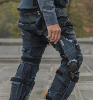 |
Frame & Strap |
| KIT-EXO-1 | 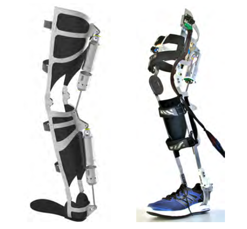 |
Velcro strap around thigh and shank |
| Quasi-Passive Knee Exoskeleton | 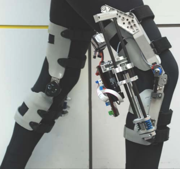 |
Cuff + Velcro |
Proposed design idea:
A kinematic strap mechanism for the thigh and calf that automatically loosens during knee flexion. As the limb bends and the muscle cross-section increases, the mechanism increases strap length or reduces tension, mitigating the tourniquet effect and improving comfort. During extension, the strap re-tightens to maintain secure coupling and reduce slippage, providing a better user experience without sacrificing control performance.
G. Control Framework (+communication)
The system will be driven using sensor inputs to a microcontroller, which then causes a motor driver to change the actuation from a motor. This feedback will be sent back to the microcontroller to ensure that the target trajectory is achieved.
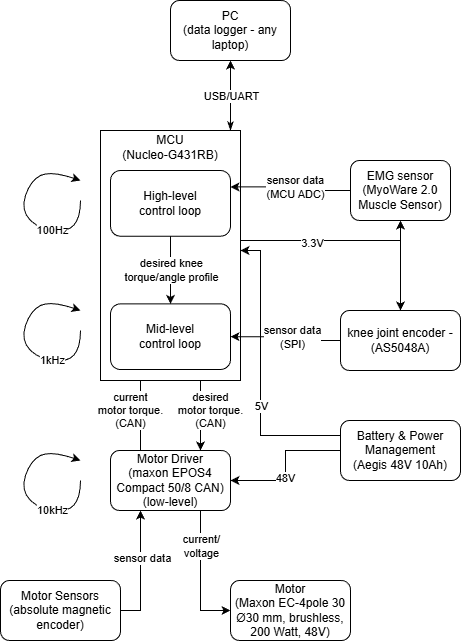
-
High-level control (running on the Nucleo-G431RB at ≈100 Hz), the MCU reads the EMG signal through its ADC and interprets user intent (e.g., level of muscle activation and gait phase). Based on this information and a stored “desired” healthy knee profile, it generates a desired knee torque/angle trajectory and overall assistance level, and sends this reference to the mid-level controller while streaming data to the PC for logging.
-
Mid-level control
The mid-level loop (≈1 kHz, also on the MCU) is a joint-level controller for the knee. It receives the desired knee torque/angle from the high-level loop and the actual knee angle from the absolute joint encoder (AS5048A over SPI), and computes the corresponding desired motor position command. This loop implements the main position/impedance control of the knee joint and sends the desired motor position to the motor driver via CAN. -
Low-level control
The low-level control is executed inside the motor driver (Maxon EPOS4, ≈10 kHz). Using the motor’s built-in sensors (current and encoder feedback), the driver closes fast current/velocity/position loops and generates current/torque input to the Maxon EC-4pole motor. It enforces current and voltage limits, providing precise tracking of the commanded motor position from the mid-level controller while protecting the hardware.
H. Evaluation
Compute the total mass of all components and the torque density. Add these masses (and scaled inertia) back into OpenSim model and evaluate the performance change (based on total muscle activation).
Table II: Total weight of components
| Component | Mass (kg) |
|---|---|
| Actuator | 0.3 |
| Kinematic Structure | |
| Link (Carbon rod, D: 5 mm) | 0.34 |
| Strap + Belt | 0.5 (0.2 + 0.3) |
| Ball screw + Frame (Ball screw: 0.4 m, D: 5 mm; Frame: 50×50×50 mm aluminum box) | 1.0 (0.3 + 0.675) |
| Electronics | |
| Motor Driver | 0.09 |
| Casing (plastic) | 0.2 |
| Battery | 2.8 |
| MCU + wires | 0.3 |
| Encoder | 0.03 |
| Total | 5.735 |
We moved the bulk of the mass distribution downstream, or farther up the leg and close to the torso, so that most of the mass is located close to the center of rotation, effectively reducing metabolic cost.
Table III: Mass distribution of the system
| Location / Components | Mass (kg) |
|---|---|
| Hip (belt) | |
| Motor Driver (0.09) | |
| Casing | |
| Battery | |
| MCU + wires | |
| Belt | 3.69 |
| Thigh | |
| Strap (half) | |
| Frame structure (half) | |
| Link (half) | |
| Ball screw | |
| Motor | |
| Encoder | 1.2875 |
| Shank | |
| Strap (half) | |
| Link (half) | |
| Frame structure (half) | 0.7575 |
Torque Density of the system:
Since the stall torque of the maxon motor is 3,430 mNm and the transmission ratio 215:1, we can assume peak torque of the system to be 737.45 Nm. Dividing this by the entire mass of the system (5.735 kg), the torque density can be calculated as 128.59 Nm/kg.
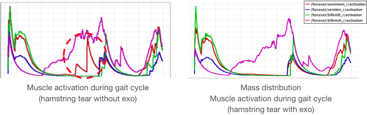
The graphs clearly demonstrate that semimembranosus activation is reduced compared to unassisted gait.
IV. Surgical Innovation
Additional anatomical techniques can be employed to improve the performance of our bionic system further.
A. Ilizarov Method
One suggested augmentation to the bionic framework takes inspiration from the Ilizarov technique, which takes inspiration from limb lengthening surgery techniques. Wires are driven into the bone, forming bone anchors. Metal halos are attached to these wires surrounding the target limb. This surgical technique provides a rigid base to which the bionic can be attached, while also solving the problem of placing undesired pressure on the affected muscle.
This technique is not well studied for its ability to withstand dynamic loading patterns, such as those sustained under walking and control inputs from our actuated system 11 12. Although potentially reversible, there may also be unwarranted bone growth at anchor sites. The surgery is also quite invasive. For these reasons, this surgery may not be the most suitable option for our given pathology.
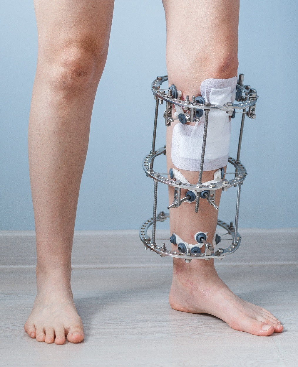
Table IV: Cost-Benefit Analysis: Ilizarov Surgical Method
| Category | Details |
|---|---|
| Procedure Type | Highly invasive; surgical implantation of external fixator |
| Cost | High; includes surgery, hospitalization, fixator hardware, follow-up visits, potential revisions |
| Recovery Time | Long; several months with fixator in place, gradual weight-bearing, and rehab |
| Risk Level | High; infection, nerve damage, non-union, joint stiffness, prolonged pain |
| Functional Outcomes | Effective bone lengthening and joint realignment; requires intensive rehab for mobility |
| Repeatability/ Adjustability | Limited; revisions require additional surgery |
| Patient Burden | High; cumbersome external fixator, frequent clinic visits, strict care required |
| Long-term Benefits | Permanent limb lengthening and deformity correction; long-term functional gain if complications avoided |
| Ideal Candidates | Patients requiring significant limb lengthening, deformity correction, or bone reconstruction |
B. Electrical Stimulation
We can also choose to augment our mechanical exo with FES/NMES co-activation 13. A hybrid physical exo and electrical stimulation approach can leverage the benefits of either method while reducing the downsides. Electrical stimulation is a low-weight and energy-efficient system, but it may introduce muscular fatigue over extended use. Mechanical exos are a rigid, controllable platform that entirely offloads muscle use, but can be physically unwieldy and heavy. A hybrid system also increases control complexity, requiring simultaneous optimization of electrical stimulation and mechanical actuation while accounting for the nonlinear biomechanics involved in walking.
Here are two methods of electrical stimulation:
-
Functional Electrical Stimulation (FES) using EMG: High-density surface electrode (HD-sEMG) array or multi-pad FES sleeve (rows of small pads) may be worn. This system may be hard to get specificity with electrical activation.
-
Neuromuscular Electrical Stimulation (NMES) via neural interfacing provides more direct access to muscle-specific activation pathways. This can be implemented with implantable electrodes (i.e., book electrodes, cuff electrodes) on tibial nerve branches.
Table V: Cost-Benefit Analysis: Electrical Stimulation
| Category | Details |
|---|---|
| Procedure Type | Non-invasive or minimally invasive; uses wearable electrodes and actuators |
| Cost | Low to moderate; equipment, clinical supervision, and rehab sessions |
| Recovery Time | Shorter; a few weeks to months depending on therapy intensity |
| Risk Level | Low; may include skin irritation, mild discomfort, or muscle fatigue |
| Functional Outcomes | Improves muscle activation, strength, and gait; limited effect on bone lengthening |
| Repeatability/ Adjustability | Highly adjustable; stimulation parameters can be modified, therapy repeated |
| Patient Burden | Low; wearable devices allow mobility, outpatient-friendly |
| Long-term Benefits | Muscle preservation, improved neuromuscular control, reduced risk of re-injury |
| Ideal Candidates | Patients needing muscle rehabilitation or gait assistance, non-surgical approach preferred |
Based on the cost-benefit analysis of both augmentative methods, electrical stimulation appears to be the more advantageous approach. It outperforms the Ilizarov method across multiple metrics, including cost, functional outcomes, adjustability, and invasiveness, making it a promising option for rehabilitation and gait assistance.
V. Conclusions
This project provides a structured foundation for understanding basic hamstring injury mechanics and exploring potential bionic assistance strategies. The compiled pathology research, anatomical modeling, and prior surgical approaches help clarify both the challenges and opportunities in supporting recovery. These insights will guide the continued development of a bio-mechanically informed, assistive bionic system aimed at enhancing joint stability, restoring strength, and reducing reinjury risk.
Appendix
Error Tracking
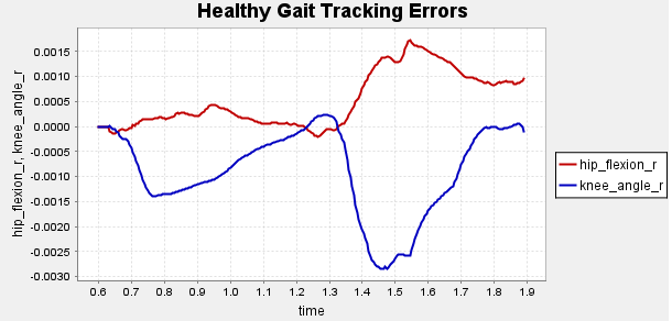
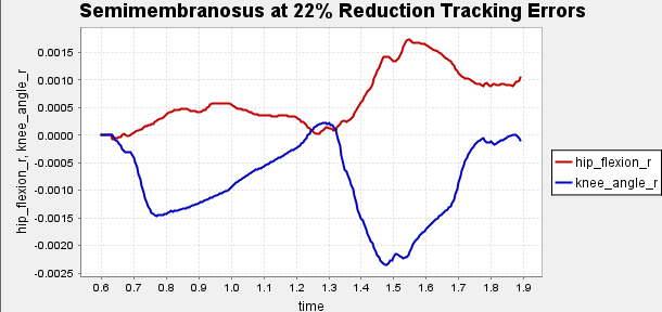
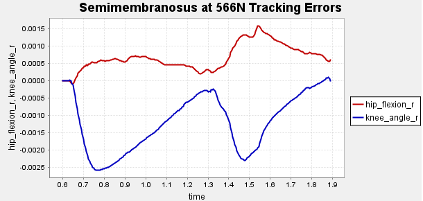
Figure A1: Error Tracking for Comparison for Final Result.
Reserve Plots

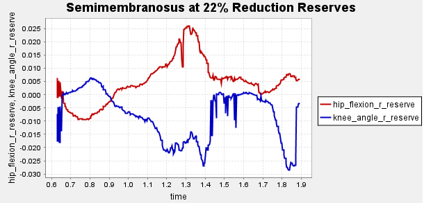
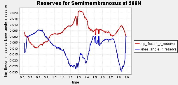
Figure A2: Reserve Plots for Comparison for Final Result.
Motor Specification Summary
Table A1: Motor Specification Summary
| Motor | $R_{\text{term}}$($\Omega$) | $L_{\text{term}}$ (mH) | $K_t$ (mNm/A) | $K_v$ (rpm/V) | Inertia (g·cm²) |
|---|---|---|---|---|---|
| ECX FLAT 42 M (Ø 42 mm) | 0.933 | 0.698 | 60.1 | 159 | 86.2 |
| ECX FLAT 32 L (Ø 32 mm) | 1.07 | 0.805 | 32.8 | 291 | 9.47 |
| EC-max 22 (Ø 22 mm, 25 W) | 13.1 | 0.729 | 34.8 | 274 | 4.45 |
| EC-4pole 30 (Ø 30 mm, 200 W) | 0.386 | 0.0653 | 27.6 | 346 | 33.3 |
| EC-4pole 30 (Ø 30 mm, 100 W) | 0.836 | 0.118 | 26.1 | 365 | 18.3 |
| ECX FLAT 32 L (with hall sensors) | 0.705 | 0.53 | 26.6 | 359 | 30.7 |
| ECX FLAT 32 L (with hall sensors) | 0.465 | 0.339 | 21.3 | 448 | 30.7 |
| ECX FLAT 32 L (with hall sensors) | 0.323 | 0.191 | 16 | 598 | 30.7 |
| EC-4pole 30 (Ø 30 mm, 200 W, 48 V) | 0.386 | 0.0653 | 27.6 | 346 | 33.3 |
| ECX FLAT 22 L (Ø 22 mm) | 6.45 | 1.12 | 30.7 | 311 | 6.82 |
| EC-4pole 22 (Ø 22 mm, 120 W) | 1.27 | 0.123 | 27.1 | 352 | 8.91 |
| EC-4pole 22 (Ø 22 mm, 90 W) | 2.37 | 0.201 | 28.1 | 340 | 5.54 |
| RE 65 (Ø 65 mm, brushed) | 0.365 | 0.161 | 123 | 77.8 | 1340 |
| EC 90 flat (Ø 90 mm, brushless) | 0.844 | 1.07 | 231 | 41.3 | 5060 |
References
Nathan Ge, Beom Jun Kim, Fotini Ioannides, Katrina Le, Matthew Silva
Department of Mechanical and Aerospace Engineering
University of California, Los Angeles
Emails: nzge@g.ucla.edu, bj007@g.ucla.edu, fotiniioannides@g.ucla.edu, katrinale@g.ucla.edu, mattsilva2@g.ucla.edu
Acknowledgement The author thanks Professor Tyler Clites for guidance and instruction throughout the MAE 263E Bionics Systems Engineering course. Their insights into bionic systems design formed the foundation of this project.
-
Radsource, “Grading hamstring injuries using the British Athletics Muscle Injury Classification (BAMIC).” [Online]. Available: https://radsource.us/grading-hamstring-injuries-using-the-british-athletics-muscle-injury-classification-bamic/ ↩ ↩2
-
OrthoIllinois, “Hamstring Tear.” [Online]. Available: https://www.orthoillinois.com/hip/hamstring-tear/ ↩ ↩2
-
Wikipedia, “Hamstring.” [Online]. Available: https://en.wikipedia.org/wiki/Hamstring#cite_note-daniel-4 ↩ ↩2
-
Wikiversity, “Medical gallery of Mikael Häggström 2014.” [Online]. Available: https://en.wikiversity.org/w/index.php?title=WikiJournal_of_Medicine/Medical_gallery_of_Mikael_H%C3%A4ggstr%C3%B6m_2014&printable=yes#Human_body_diagrams ↩ ↩2
-
H. Gray, Anatomy of the Human Body, 1918. [Online]. Available: https://archive.org/details/anatomyofhumanbo1918gray/page/960/mode/2up?q=hamstring ↩ ↩2
-
J. L. Sanfilippo, A. Silder, M. A. Sherry, M. J. Tuite, and B. C. Heiderscheit, “Hamstring strength and morphology progression after return to sport from injury,” Med. Sci. Sports Exerc., vol. 45, no. 3, pp. 448–454, Mar. 2013. [Online]. Available: https://pmc.ncbi.nlm.nih.gov/articles/PMC3580023/ ↩ ↩2 ↩3
-
B. Schmitt, T. Tim, and M. McHugh, “Hamstring injury rehabilitation and prevention of reinjury using lengthened state eccentric training: a new concept,” Int. J. Sports Phys. Ther., vol. 7, no. 3, pp. 333–341, Jun. 2012. [Online]. Available: https://pmc.ncbi.nlm.nih.gov/articles/PMC3362981/ ↩ ↩2
-
B. Poudel and S. Pandey, “Hamstring Injury,” StatPearls [Internet], Treasure Island, FL: StatPearls Publishing, 2023. [Online]. Available: https://www.ncbi.nlm.nih.gov/books/NBK558936/ ↩ ↩2
-
S. E. Wong, K. R. Julian, J. G. Carpio, and A. L. Zhang, “Proximal hamstring repair with all-suture anchors and an accelerated rehabilitation and bracing protocol demonstrates good outcomes at 1-year follow-up,” Arthrosc. Sports Med. Rehabil., vol. 6, no. 2, 100891, Feb. 2024. [Online]. Available: https://pmc.ncbi.nlm.nih.gov/articles/PMC10867423/ ↩ ↩2
-
OpenSim Confluence, “Gait 2392 and 2354 Models.” [Online]. Available: https://opensimconfluence.atlassian.net/wiki/spaces/OpenSim/pages/53086215/Gait+2392+and+2354+Models ↩ ↩2
-
A. L. Author et al., “Direct and indirect loading of the Ilizarov external fixator: the effect on the interfragmentary movements and compressive loads,” J. Orthop. Surg. Res., [Online]. Available: https://pmc.ncbi.nlm.nih.gov/articles/PMC3058184/ ↩ ↩2
-
Oxford Orthopaedics, “Limb lengthening and reconstruction surgery.” [Online]. Available: https://oxfordortho.sg/limb-lengthening-and-reconstruction-surgery/ ↩ ↩2
-
Author(s), “Hybrid FES–robot cooperative control of ambulatory gait rehabilitation exoskeleton,” [Online]. Available: https://link.springer.com/article/10.1186/1743-0003-11-27 ↩ ↩2
-
MedlinePlus, “Hamstring muscle,” Patient Instructions. [Online]. Available: https://medlineplus.gov/ency/patientinstructions/000551.htm ↩
-
NCBI MeSH, “Hamstring,” 2016. [Online]. Available: https://www.ncbi.nlm.nih.gov/mesh/2016304 ↩
-
TeachMeAnatomy, “Hamstrings.” [Online]. Available: https://teachmeanatomy.info/lower-limb/muscles/thigh/hamstrings/ ↩
-
Merriam-Webster, “Hamstring.” [Online]. Available: https://www.merriam-webster.com/dictionary/hamstring ↩
-
Wikipedia, “Linea aspera.” [Online]. Available: https://en.wikipedia.org/wiki/Linea_aspera ↩
-
Wikipedia, “Biceps femoris muscle.” [Online]. Available: https://en.wikipedia.org/wiki/Biceps_femoris_muscle ↩
-
Netter Images, “Gluteal and posterior thigh muscles (unlabeled).” [Online]. Available: https://www.netterimages.com/gluteal-and-posterior-thigh-muscles-unlabeled-76263.html ↩
-
Musculoskeletal Key, “Limb lengthening using the Ilizarov method or a monoplanar fixator.” [Online]. Available: https://musculoskeletalkey.com/limb-lengthening-using-the-ilizarov-method-or-a-monoplanar-fixator/ ↩
-
International Center for Limb Lengthening, “Short Stature: Want to Be Taller? (Cosmetic Height Surgery).” [Online]. Available: https://www.limblength.org/conditions/short-stature/ ↩