Design of a Micro-Mirror Compliant Mechanism
Winter 2026 MAE C294A
Liliana Figueroa Perez, Ryan Fukunaga, Ethan Freed, Nathan Ge, Avi Gerber
Abstract
This paper explores flexure-based micro-mirror design through a review of pre-existing approaches and a collaborative try at micro-mirror topology synthesis. More specifically, our flexure-based micro-mirror design can translate (i.e. piston) up and down to be used to modulate the phase of light reflected off from its surface for a variety of high-impact precision applications (e.g., adaptive optics). Such mirrors are often driven to operate at their resonant frequencies to minimize the system’s required actuation energy and to simplify the mirror’s control such that no sensors or closed-loop control circuitry is necessary to achieve the desired speed. Therefore, our goal is to use topology synthesis as the design basis for a flexure-based compliant mechanism that acts as a precise, purely translational pistoning mirror stage operating at high speeds.
This paper introduces micromirror systems and its technical background, our micro-mirror design objectives and the associated design approach (FACT), analytical validation of modal frequencies, and concludes with our design’s intended fabrication approach.
I. Background
Introduction
At the core of modern optical systems exist tiny movable mirrors; micromirrors coupled together on chips to form Micromirror Arrays (MMA). Micromirrors are Micro-Electro-Mechanical System (MEMS), or mechanisms that may include springs and levers with electronics that operate on the microscopic level 1. The scale and precision at which these systems operate creates its own unique set of engineering challenges especially in fabrication. Fundamentally, each small mirror moves precisely in order to manipulate light waves in useful ways, such as steering, changing its direction, or adjusting its phase. The precise light manipulation capabilities of this class of MEMS have proven to be extremely valuable to a wide range of technological fields, such as high-speed internet, telescopes/astronomy, and the medical field with advanced biological imaging.
A notable modern use case is Light Detection and Ranging (LiDAR) for self-driving cars. Self-driving cars, such as Waymo, use LiDAR sensing systems as their primary “eyes” 2. LiDAR sends rapid laser pulses and captures the time of reflection off surrounding objects and its return path (time of flight). The time of flight of dispersed laser beams uniformly distributed and sampled across a spherical space generates a point cloud that represents the external surfaces of objects in the local vicinity. This helps create a detailed and precise 3D mapping of the surrounding environment and its existing features, including vehicles and people, enabling collision avoidance and precise navigation. By using MEMS mirrors to quickly and accurately steer the laser beam, the system can scan and interpret an entire field at speeds required for navigation control.
Technical Breakdown
On a technical level, the vast majority of micromirrors are compliant mechanisms. They consist of a rigid stage, or the mirror, connected to a fixed ground by flexures. Rather than rigid mechanisms that transfer or redirect motion and energy through rigid interlocking structures, compliant mechanisms use elastic deformation to create motion through the flexures.
At the micro-scale, compliant mechanisms are preferred over traditional rigid-body joints as they eliminate friction and wear, thereby mitigating non-linear effects such as hysteresis. These parasitic phenomena are significantly more pronounced at smaller scales, where surface forces dominate over inertial forces. Consequently, the inherent precision of compliant architectures is essential for meeting the stringent motion requirements of micro-scale applications. As long as desired compliant movement of the mechanism falls within the elastic regime of the material, smooth, precise, repeatable motion is achieved even at high speeds. The micromirror’s function must guarantee movement permittance and subsequent unwanted movement rejection, high bandwidth tracking, minimizing unintended behaviors, and a reliable mode of actuation.
The flexures are designed to be stiff in some directions and compliant in others. Compliant modes of movement define the mechanism’s degrees of freedom (DOF). Our micromirror is designed to move with a single specific translational DOF, piston motion (move purely up and down, translating perfectly orthogonal to its reflective surface). This movement changes the distance that light travels before it is reflected, or optical path length, the phase of the light wave. DOF permittance can be procedurally tuned using the FACT method, outlined in the topology portion of the paper.
As mentioned before, micromirrors must achieve precise movements at high speeds. Micromirrors are often applied in situations that require reference signal tracking and disturbance rejection at incredible speeds. We need a high-bandwidth system to follow fast-changing inputs. At the core physical principles, this means a system that has high mechanical resonant frequency ($f = \sqrt{k/m}$) to enable high speed and high acceleration tracking while avoiding resonance amplification at low frequency movements. Lowering dynamic mass ($m$) and increasing stiffness ($k$) are crucial in achieving this effect.
One of the most prominent challenges is parasitic tilt, which is unwanted rotational piston movement. This often occurs when there are uncontrolled degrees of freedom within the flexures if they are not stiff enough. In order to minimize this, designers use complex geometries such as double S-shaped unimorph actuators to maintain proper alignment.
To drive compliant mechanisms, actuation methods must not counteract the design strengths of compliant mechanisms, which is to enable smooth, precise, repeatable motion. This is why non-contact actuation methods such as electrostatic plates, comb drives, or thermal beams are used to drive MEMS micromirrors. When a voltage is applied to the system, the actuators create a force that either pushes or pulls the mirror, which then causes the flexures to bend and move the mirror to its intended position.
Case Study: The Fraunhofer Mirror
A relevant existing design that focuses on achieving a single piston DOF using resonant actuation is the Fraunhofer IPMS Translatory Mirror (Figure 1), also known as the “Translatory MEMS Mirror with Extraordinary Large Stroke (Pump Mode)” 3. This device was created to provide fast modulation of optical path length for high-precision optical metrology systems.
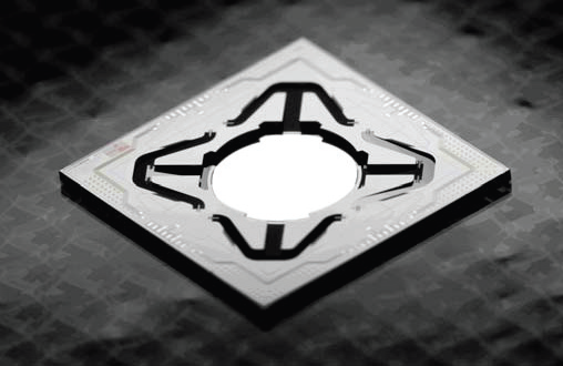
The Fraunhofer mirror is designed to move up and down very quickly, changing the distance light travels before returning. This creates a controlled phase shift in the reflected light. It is essentially a small high-speed optical ruler that can make extremely precise measurements.
Axially symmetric pantograph suspension flexures (which are categorically a collection of wire flexures and blade flexures) work together to guide the mirror and maintain its orientation as it moves up and down. The flexures are compliant in the piston direction but are also stiff in all other directions in order to ensure there are no unwanted rotational movements.
This symmetric design helps achieve large vertical displacements while still being able to maintain stable and predictable motion. Additionally, the mirror is designed to undergo high vibrations and shock insensitivity. This makes it a great candidate for both laboratory and industrial applications such as medical imaging and LiDAR.
Instead of having the mirror at static positions, the Fraunhofer design applies a harmonic driving signal tuned specifically to the natural frequency of the mirror’s piston mode. When the driving signal matches the natural frequency, the amplitude of the mirror’s motion is significantly amplified. Essentially, the mirror leverages its own natural vibration to create more motion. Subsequently a high mechanical advantage with minimal power usage not possible using standard actuators is achieved. However, resonant designs come with their own set of problems, such as a restriction to sinusoidal patterns and an inability to hold static positions. They are better suited for continuous repetitive motion.
II. Topology
The determination of flexure position, orientation, and type selection was governed by a hierarchy of design requirements centered on the moving stage.
Design Objectives
The primary objective of the system is to permit the mirror to achieve a single translational pistoning motion. Secondary objectives, which ensure real-world performance and structural integrity, are detailed in Table I.
| Objective | Reasoning |
|---|---|
| Maximize $f_n$ (1st mode) | Allows the mirror to resonate at the highest possible operating speed. |
| Frequency Separation | All parasitic natural frequencies (rad/s) must be at least one order of magnitude (10×) larger than the first natural frequency to prevent unwanted DOFs. |
| Maximize Modal Gap | Prevents cross-excitation of unwanted modes during high-speed operation, ensuring dynamic stability. |
| Minimize Parasitic Error | Ensures light is not redirected by unintended tipping or tilting motions during large-range translation. |
| Manufacturing Feasibility | Increases likelihood of design adoption and production at scale. |
Table I: Design Objectives and Engineering Rationale
Topology Synthesis via FACT
The topology synthesis pipeline follows the Freedom and Constraint Topology (FACT) approach. Guidelines for the mode of constraint and freedom (DOFs) were sourced from the FACT library, which categorizes compliant mechanisms into specific groupings. The desired movement pattern aligns with the 1 DOF Type 3 freedom space. The associated freedom and constrain spaces are shown in Figures 4 and 5 respectively. Flexures were positioned in accordance with the associated constraint space of this grouping. Serial and hybrid systems were disregarded in favor of a simpler parallel system to adhere to the “Keep It Simple, Stupid” (KISS) principle.


Constraint Analysis
The use of multiple blade flexures results in an overconstrained system. Each blade flexure provides an order of constraint of 3. For a system with 4 blades:
\[C_{\mathrm{total}} = 4 \times 3 = 12\]Given that the target constraint space for this DOF is 5, the degree of overconstraint ($O$) is calculated as:
\[O = C_{\mathrm{total}} - \mathrm{DOF}_{\mathrm{constraint}} = 12 - 5 = 7\]The system is overconstrained by 7 degrees of freedom. This trade-off is accepted to maximize off-axis stiffness and maintain the required symmetry for high-speed precision.
System Architecture and Redundancy
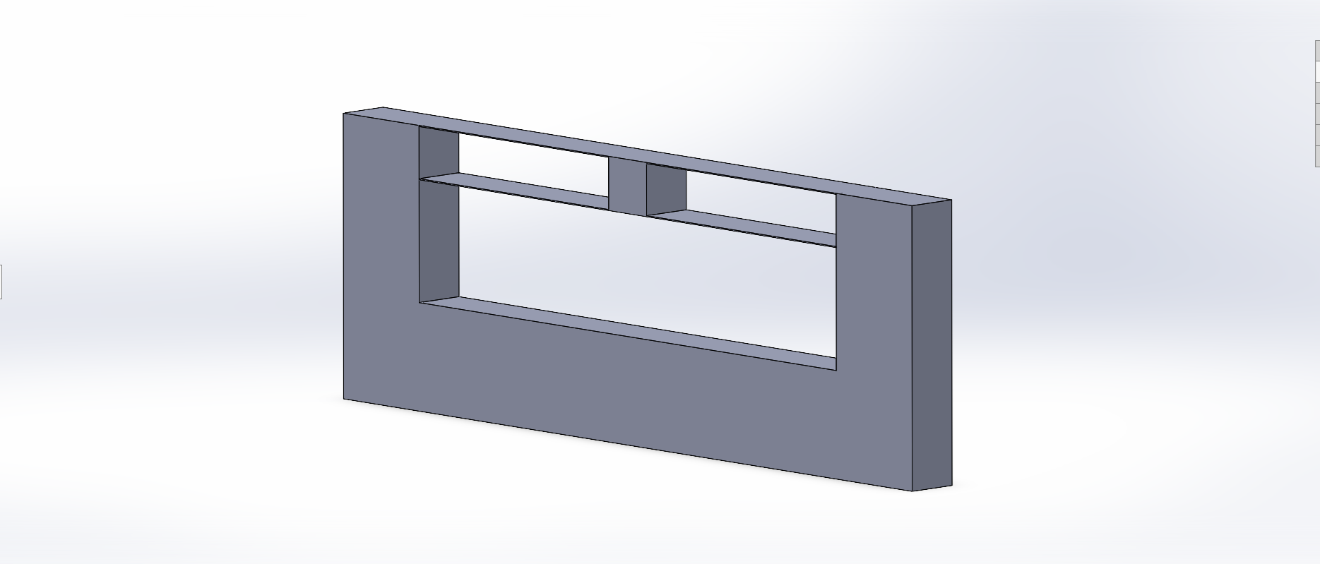
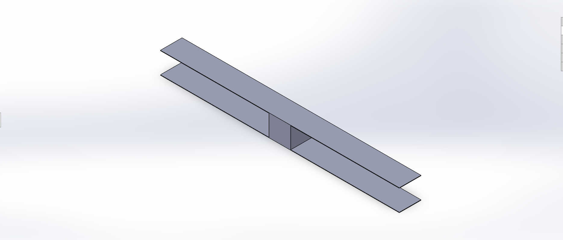
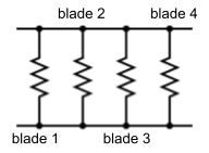
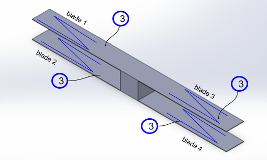
The resulting compliant system consists of two pairs of blade flexures placed on opposing sides of a stage block. This symmetric, redundant structure provides several advantages:
- Buckling Mitigation: Redundant structures preserve directional compliance while significantly improving load capacity.
- Dynamic Bandwidth: Stiffness is increased without a proportional increase in mass. As the natural frequency is defined by $\omega_n = \sqrt{k/m}$, this results in a higher dynamic bandwidth.
- Error Attenuation: Axial symmetry attenuates parasitic error and thermal instability. The redundancy corrects the natural arcing path of a single blade into true linear translation.
- Thermal Robustness: Symmetrical expansion rates ensure the stage remains on the desired path despite temperature fluctuations.
III. Modal Analysis
Calculations
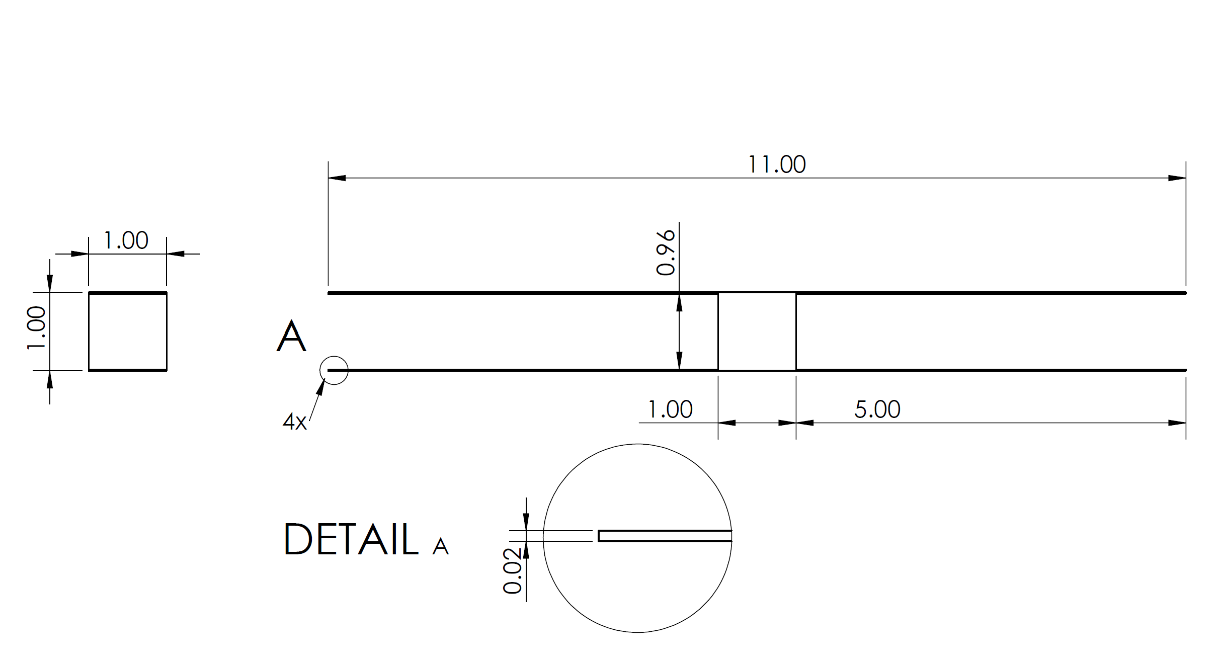
The dynamic behavior of the proposed micro-mirror system was analyzed using a MATLAB model. The stiffness matrix of the flexure system was generated using the provided EulerStiffnessMatrix function, which uses twist-wrench vector analysis to generate the system stiffness matrix for each blade flexure based on its geometry, orientation, and material properties. The mirror stage mass matrix was constructed directly from the stage dimensions, density, and corresponding mass moments of inertia.
The stage mass matrix was assembled using a coordinate transformation of the form
\[M = N \,\Delta I\, N^{-1}\]where $N$ is the transformation matrix, $\Delta$ represents the mass distribution, and $I$ is the inertia matrix.
With both matrices defined, the natural frequencies and mode shapes were found by solving for the system eigenvalues using
\[M^{-1} K \mathbf{x} = \lambda \mathbf{x}\]where $\lambda = \omega^2$. Taking the square root of the eigenvalues gives the angular natural frequencies of the system, which is then divided by $2\pi$ to convert from units of rad/s to Hz. This allowed the primary piston mode to be identified and the separation between the first and higher-order modes to be evaluated, ensuring that unwanted modes remain sufficiently suppressed relative to the desired motion. The first two calculated resonant frequencies and corresponding mode shapes are
\[f_1 = 559.3\ \mathrm{Hz}, \qquad \mathbf{x}_1 = \begin{bmatrix} 0 \\ 0 \\ 0 \\ 0 \\ 1\,\mathrm{m} \\ 0 \end{bmatrix}\] \[f_2 = 27{,}965.0\ \mathrm{Hz}, \qquad \mathbf{x}_2 = \begin{bmatrix} 0 \\ 0 \\ 0 \\ 1\,\mathrm{m} \\ 0 \\ 0 \end{bmatrix}\]FEA Verification
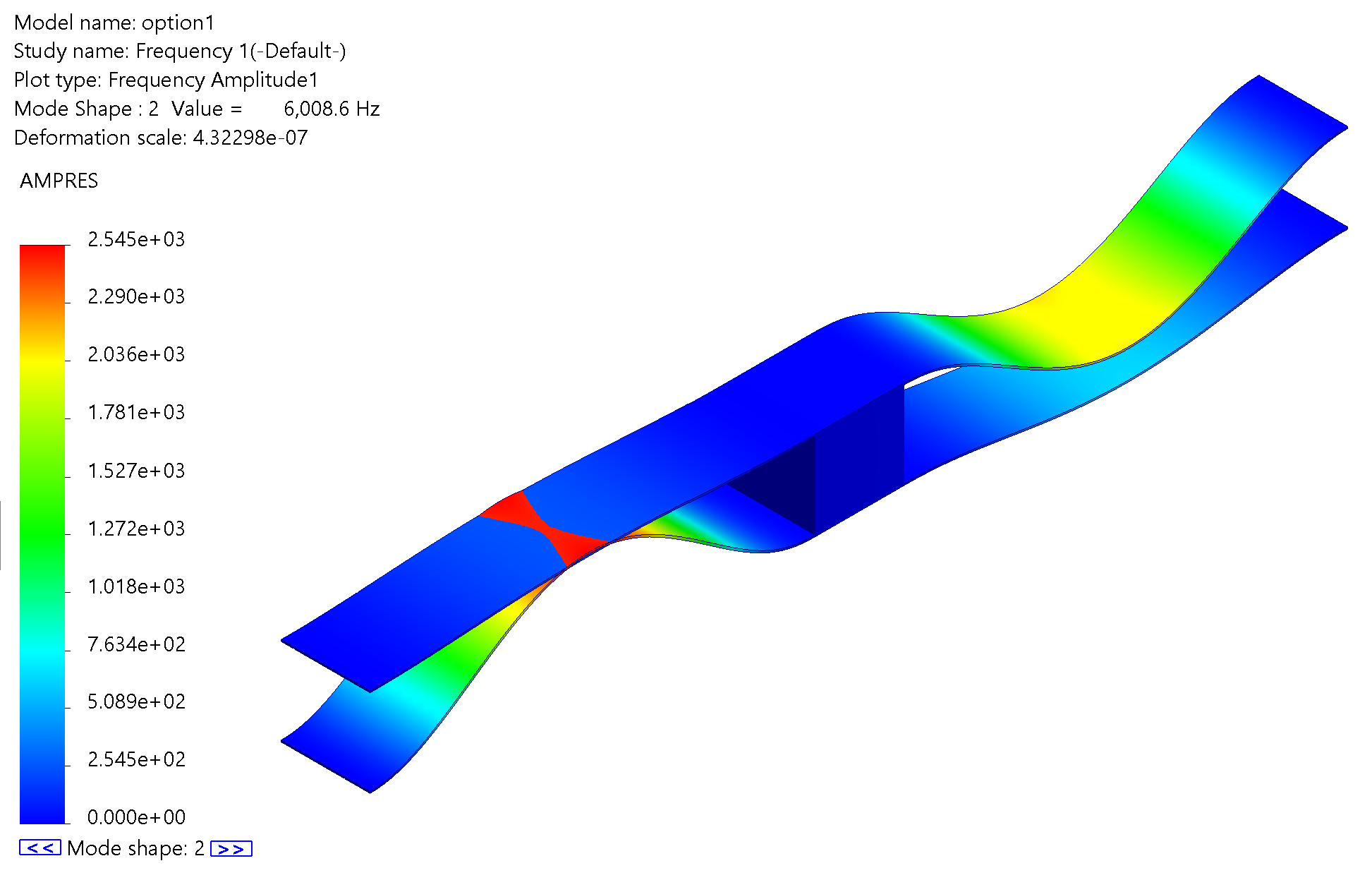
The first two resonant frequencies obtained from the MATLAB calculations are 559.3 Hz and 27,965.0 Hz, while the FEA simulation yields corresponding values of 543.5 Hz and 6008.6 Hz. In both cases, the second natural frequency is more than 10 times greater than the first, with the FEA simulation yielding an 11× increase, and the MATLAB simulation as large as 50×. This large separation indicates that the system is dominated by a single mode of motion, confirming that the mirror primarily operates with one degree of freedom and is unlikely to experience significant motion in unintended directions.
Additionally, the first mode shape eigenvector from the analytical calculation corresponds to an upward translation in the positive $y$-direction, which is normal to the blade flexure surfaces. This behavior is consistent with the intended design and is visually confirmed in Figure 8.
The first resonant frequency has a percent difference of approximately 2.8%, while the second has a percent difference of approximately 78.5%. The second frequency is less critical since the system is designed to operate with a single degree of freedom. The large discrepancy in the second resonant frequency may be due to the mass of the blade flexures not being accounted for in the MATLAB model. Additionally, it is worth noting that in the SolidWorks simulation for the second mode, the blade flexures appear to pass through one another (Figure 9), indicating a non-physical deformation behavior in that mode.

IV. Fabrication Approach
Procedure
To achieve the microscale precision required for high-frequency mirror translation, a multi-step surface and bulk micromachining process is employed.
- Substrate Preparation: A standard Silicon-on-Insulator (SOI) wafer is prepared with a specific device layer thickness corresponding to the desired flexure height.
- Photolithography: A photoresist layer is spin-coated and patterned via UV exposure to define the mirror plate and flexure geometries.
- Anisotropic Etching: DRIE is utilized to etch through the device layer, ensuring vertical sidewalls for the blade flexures.
- Secondary Patterning: A second photoresist layer is applied and patterned to define the electrode and piezoelectric regions.
- Piezoelectric Integration: The active layers are deposited via sputtering or Chemical Solution Deposition (CSD).
The fabricated version of the flexure with its base is shown in Figure 10.

Piezoelectric Actuation Stack
The system utilizes non-contact piezoelectric actuation. The material is poled in the $d_{31}$ direction; specifically, an electric field applied across the thickness of the beam (the transverse direction) induces a mechanical strain in the orthogonal longitudinal direction, creating a torsional bending in the flexure blade. Unified bending of all four flexure blades in a coordinated direction drives pistoning motion.
The thin-film stack is deposited onto the single-crystal silicon device layer in the following order (from top to bottom):
- Top Electrode: Platinum (Pt), Gold (Au), or Aluminum (Al)
- Piezoelectric Film: Lead Zirconate Titanate (PZT) or Aluminum Nitride (AlN)
- Bottom Electrode: Platinum (Pt), Molybdenum (Mo), or Titanium/Platinum (Ti/Pt)
- Device Layer: Single-crystal Silicon (Si) — Forms the beams and mirror plate
- Buried Oxide (BOX): Silicon Dioxide (SiO₂)
- Handle Wafer: Bulk Silicon (Si)
V. Conclusion
To summarize, this report detailed the design, fabrication, and analysis of a high-speed, flexure-based micromirror mechanism optimized for pure translational, or piston, motion. Using the Freedom and Constraint Topology (FACT) method, a symmetric, parallel system of four blade flexures was designed to maximize off-axis stiffness and ensure stable, repeatable motion. This approach addresses key challenges in compliant mechanism design by minimizing parasitic tilt and error attenuation through deliberate overconstraint and axial symmetry. Computational modeling in MATLAB and SolidWorks finite-element analysis confirmed that the system achieves high mechanical resonant frequencies and sufficient modal separation, both essential for precision applications such as LiDAR and adaptive optics. Finally, the outlined surface and bulk micromachining process, integrated with a piezoelectric actuation stack, provides a clear and realistic pathway for fabricating these devices with the necessary microscale precision.
Author Contributions
- Avi: Topology synthesis, CAD verification, and fabrication process design.
- Ryan & Ethan: MATLAB computational analysis and modeling.
- Nathan & Lily: Synthesis of findings, formatting, and final report writing.
References
Nathan Ge
Department of Mechanical and Aerospace Engineering
University of California, Los Angeles
Email: nzge@g.ucla.edu
Acknowledgment
Thanks to Professor Hopkins for guidance and instruction throughout the MAE C294A Compliant Mechanisms course.
-
Y. Song, R. M. Panas, and J. B. Hopkins, “A review of micromirror arrays,” Precision Engineering, vol. 51, pp. 729–761, 2018. [Online]. Available: https://www.sciencedirect.com/science/article/pii/S0141635917302210 ↩ ↩2
-
J. Kim, B.-j. Park, and J. Kim, “Empirical analysis of autonomous vehicle’s lidar detection performance degradation for actual road driving in rain and fog,” Sensors, vol. 23, no. 6, p. 2972, Mar 2023. ↩ ↩2
-
T. Sandner and I. Schedwill, “Lamda large aperture mems scanner module for 3d distance measurement,” Fraunhofer Institute for Photonic Microsystems (IPMS), Dresden, Germany, Tech. Rep., July 2025, technical Datasheet M3 Lanida EN 2025-07. [Online]. Available: https://www.ipms.fraunhofer.de ↩ ↩2