Tilt-Rotor Drone

This was my attempt at creating a tilt-rotor drone inspired by Sova’s drone in Valorant.
Prototyping
Inspiration
Concept Drawings
Hardware
Components
| Item | Description |
|---|---|
| LiPo Battery | Power source |
| ESC (electronic speed control) | Takes desired motor inputs from teensy to control and regulate the speed of motors |
| UBEC (universal battery elimination circuit) | Converts LiPo battery’s higher source voltage into usable power for teensy and Raspberry Pi Pico |
| Brushless Motors | Primary source of thrust/locomotion |
| Servos | Tilts the motors to enable thrust vectoring |
| Propellors | Attached to the motors for thrust production |
| Teensy 4.0 | Low-level stabilization control |
| Raspberry Pi Pico | High-level controller that feeds control inputs to the teensy from the raspberry pi web server. Relays telemetry data from the teensy back to the web server |
| Raspberry Pi 5 | Hosts web server that provides a gui for sending control inputs to the drone via pico. Data/telemetry visualization |
| MPU 6050 | IMU for stability control |
Schematic

Design Considerations
I performed rough calculations to source motors that could support the weight of the drone.
Basic Motor Thrust Requirement Calculations
![]()
Frame

Aesthetic Components
Drone mask modeled in Blender
Tilt Mechanism
Software
Sensor Feedback and Stability Control
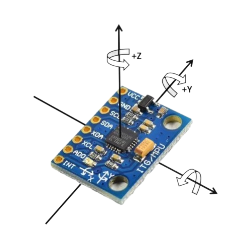
MPU6050
The MPU6050 is a 6-axis (3-axis Gyroscope, 3-axis Accelerometer) motion tracking sensor, detecting changes in acceleration and rotation.
MPU6050 Source Code
MPU6050 Class structure
#ifndef MPU6050_H
#define MPU6050_H

#include <Arduino.h>
#include <Wire.h>
#include <tuple>
#include "constants.h"

class MPU6050{
  public:
    MPU6050();
    void init();
    void calibrate();
    std::tuple<float, float, float, float, float, float> read();
    std::tuple<float, float, float> acc_read();
    std::tuple<float, float, float> gyro_read();
  private:
    float_t Ax, Ay, Az;
    float_t Gx, Gy, Gz;
    float_t Ax_cal, Ay_cal, Az_cal;
    float_t Gx_cal, Gy_cal, Gz_cal;
};

#endif
MPU6050 instantiation and startup sequence. This involves manipulating config registers to set appropriate MPU6050 settings and calibrating the sensor.
#include <Arduino.h>
#include <Wire.h>
#include <tuple>

#include "MPU6050.h"
#include "constants.h"

MPU6050::MPU6050() {
  Ax_cal = 0;
  Ay_cal = 0;
  Az_cal = 0;
  Gx_cal = 0;
  Gy_cal = 0;
  Gz_cal = 0;
}

void MPU6050::init() {
  Wire.beginTransmission(0x68); // MPU6050 I2C address
  Wire.write(0x6B);  // Power management register
  Wire.write(0x00);  // Wake up MPU6050
  Wire.endTransmission();

  // Set Digital Low Pass Filter (DLPF)
  Wire.beginTransmission(0x68);
  Wire.write(0x1A); // DLPF config register
  Wire.write(0x05); // 10 Hz cutoff frequency
  Wire.endTransmission();

  // Configure Gyro (±500°/s range)
  Wire.beginTransmission(0x68);
  Wire.write(0x1B); // Gyro config register
  Wire.write(0x08); // Set range (65.5 LSB/deg/s)
  Wire.endTransmission();

  // Configure Accelerometer (±2g range)
  Wire.beginTransmission(0x68);
  Wire.write(0x1C); // Accel config register
  Wire.write(0x00); // Set range (16384 LSB/g)
  Wire.endTransmission();

  calibrate();
}
This function is responsible for gathering gyrometer and accelerometer readings from the MPU6050.
std::tuple<float, float, float, float, float, float>  MPU6050::read(){
  Wire.beginTransmission(0x68);
  Wire.write(0x3B); // Starting register for accelerometer data
  Wire.endTransmission(false);

  Wire.requestFrom(0x68, 14); // Request 14 bytes
  int16_t rawAx=Wire.read()<<8 | Wire.read();
  int16_t rawAy=Wire.read()<<8 | Wire.read();
  int16_t rawAz=Wire.read()<<8 | Wire.read();
  int16_t temp=Wire.read()<<8 | Wire.read();
  int16_t rawGx=Wire.read()<<8 | Wire.read();
  int16_t rawGy=Wire.read()<<8 | Wire.read();
  int16_t rawGz=Wire.read()<<8 | Wire.read();

  float_t Ax = (float)(rawAx) / LSB_acc - Ax_cal; // convert to G
  float_t Ay = (float)(rawAy) / LSB_acc - Ay_cal;
  float_t Az = (float)(rawAz) / LSB_acc - Az_cal;
  float_t Gx = (float)(rawGx) / LSB_gyr - Gx_cal;
  float_t Gy = (float)(rawGy) / LSB_gyr - Gy_cal;
  float_t Gz = (float)(rawGz) / LSB_gyr - Gz_cal;

  return std::make_tuple(Ax, Ay, Az, Gx, Gy, Gz);
}
Calibration
The MPU6050 is calibrated by sampling 1000 gyroscope and accelerometer readings at a stationary position. One thing to note is that the accelerometer in the z-axis is calibrated to -1g to account for the constant pull of gravity, while all other values are calibrated to 0.
//calibration sequence
void MPU6050::calibrate() {
  float_t sumAx = 0, sumAy = 0, sumAz = 0;
  float_t sumGx = 0, sumGy = 0, sumGz = 0;
  // Collect accelerometer and gyro data to compute offsets
  for (int i = 0; i < calibrationSamples; i++) {
    auto [ax, ay, az, gx, gy, gz] = read();
    // Sum the errors for each axis
    sumAx += ax;
    sumAy += ay;
    sumAz += az;
    sumGx += gx;
    sumGy += gy;
    sumGz += gz;

    delay(10); // Small delay between readings
  }

  // Calculate average errors
  Ax_cal = sumAx / calibrationSamples;
  Ay_cal = sumAy / calibrationSamples;
  Az_cal = (sumAz / calibrationSamples) - 1; // Subtract 1g from Z axis
  Gx_cal = sumGx / calibrationSamples;
  Gy_cal = sumGy / calibrationSamples;
  Gz_cal = sumGz / calibrationSamples;

  // Print calibration results
  Serial.println("Calibration done");
  Serial.print("Acc Errors: ");
  Serial.print(Ax_cal);
  Serial.print(" ");
  Serial.print(Ay_cal);
  Serial.print(" ");
  Serial.println(Az_cal);

  Serial.print("Gyro Errors: ");
  Serial.print(Gx_cal);
  Serial.print(" ");
  Serial.print(Gy_cal);
  Serial.print(" ");
  Serial.println(Gz_cal);
}
Sensor Fusion
Sensor fusion is used to convert 6-axis MPU readings (yaw rate, pitch rate, roll rate from gyrometer and $\dot{x},\dot{y},\dot{z}$ from accelerometer) to obtain precise global yaw, pitch, and roll angle estimations. These angle values are important to stabilize and move the drone in desired ways through subsequent algorithmic steps. Sensor fusion also mitigates the impact of sensor drift when the MPU sensor cannot perfectly maintain perfect 0 readings at stationary position. A few sensor fusion approaches were explored, with the simplest being a complementary filter. Madgwick, Mahony, kalman, and extended kalman filters were also potential candidates.
PID
Current global rotational positions computed through sensor fusion is fed into a PID controller, which performs error correction to achieve the desired orientation of the drone. Current global rotational positions of the MPU6050 is compared to a nominal orientation to compute error and subsequently correct for that error. The nominal orientation is recieved by the PID controller through a higher level controller.
Positional Control
Positional control is handled via wireless communication thorough the Raspberry Pi Pico. The Raspberry Pi Pico recieves control inputs from the Raspberry Pi wirelessly and relays it to the teensy.
Motor mixing
Motor mixing is the act of taking the orientation desired by our high-level and low-level controllers and computing the necessary motor inputs to achieve the expected orientation. Motor mixing varies from drone-to-drone or robot-to-robot depending on your control configuration.
Temeletry and Visualization
OpenGL/WebGL
Real-time rotation visualization
Build Log
5-21-25:
2-25-25: IMU works but experiencing gyro drift
Quadcopter Race Drone
Hardware Design
Components
Schematic
Build Log
5-25-25:
5-21-25:
References
Inspiration
V22 Osprey by Tom Stanton
Flight Controller
RC VTOL - V4 by Tom Stanton
2. Control of Drone (Quadcopter) DC Motors Using Teensy/Arduino - Aleksandar Haber PhD
Embedded Programming for Quadcopters - Code and Supply
Drone Performance Optimization and Component Selection 10 Ways to Make Your Drone Lighter - Improve Your Quadcopter’s Performance - Timmy RC How to Reduce Weight of FPV drones – make them lighter and fly better - Oscar Liang Using LiPo Batteries for FPV Drones: Beginner’s Guide with Top Product Recommendations - Oscar Liang
- Lookup Table: Motor & Prop Sizes, KV, Battery Cell Count, and Weight for FPV Drone Builds How to Choose FPV Drone Motors – Considerations and Best Motor Recommendations - Oscar Liang
Sources
[^1]: “How I Designed a 3D Printed Wing”, Accessed March 6, 2025.