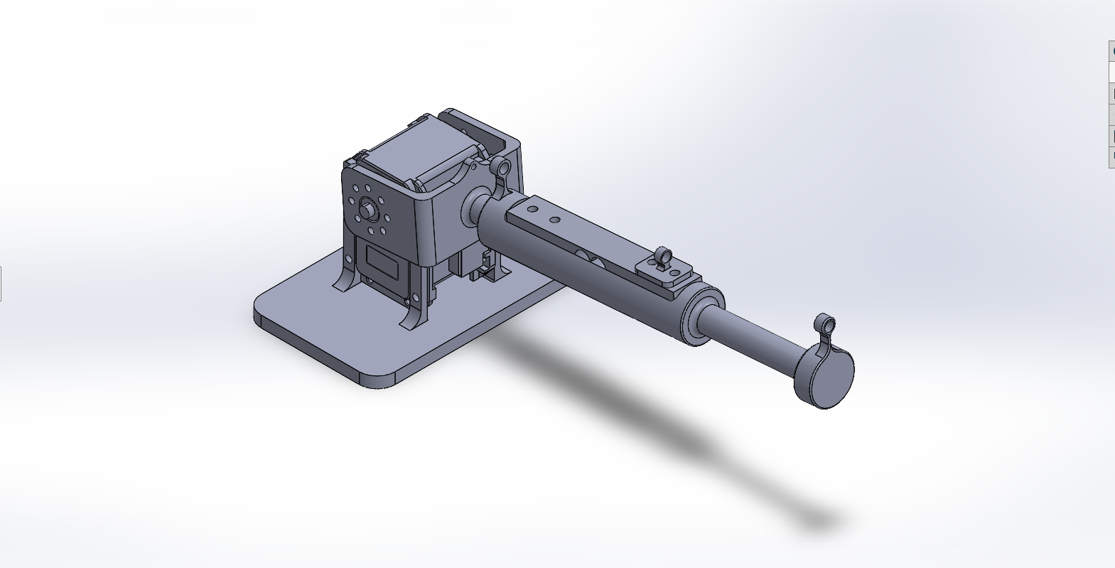
Autonomous Robotic Fishing Line Tension Regulation Using Admittance Control
Spring 2026 MAE 263C
Nathan Ge, Chaoyi Hu, Julie Nguyen, Xiang Zhou
Abstract
This project presents an autonomous robotic fishing system focused on post hook-set tension regulation as a force control problem. After a fish is hooked, maintaining line tension requires balancing overpulling, which risks snapping the line, against underpulling, which can lose the fish. The platform is a one degree-of-freedom robotic rod that measures fishing line tension with a load sensor and uses an admittance controller to convert tension feedback into rod pitch motion. The control architecture combines tension-based regulation with position compensation and an engagement supervisor that manages transitions between idle, active control, and recovery states. The system is implemented in a ROS2 software stack and validated first in MuJoCo simulation with a repeatable fish-like disturbance, then on hardware with manual line tension trials. Simulation and hardware experiments show that the robot responds intelligently to changing line tension rather than applying fixed motor commands. This work demonstrates a practical foundation for sensor-driven tension regulation in robotic fishing and motivates future extensions to multi-DOF systems, improved state switching, and more complete autonomous fishing pipelines.
I. Overview
This project explores the potential of an autonomous robotic fishing framework. To carry the problem into an engineering lens and build a technical framework around it, the robot’s function was centered on the fishing line tension aspect of the fishing pipeline, which is modeled as a force control problem.
Tension regulation is fundamentally characterized by the balance of overpulling, which risks the line snapping, and underpulling, which can lose the fish. Good anglers respond by dynamically adjusting the orientation of the rod with intuition and feel, keeping the line tension in a safe zone. The robot performs this balancing act intelligently with sensor feedback and precise motor control.
Related Work
Similar robotic fishing systems have been explored previously. AlYaseen et al. developed an autonomous fishing rod that can detect fish bites, pull the line, and stop the motor when high resistance is detected to avoid cutting the line 1. This is closely related to this project because both systems use the fishing-line force as an important feedback signal. Another robotic fishing pole project used an Arduino-controlled mechanical system to cast and reel automatically through smartphone or computer control 2. These examples show that fishing is a suitable application for automation and robotic actuation.
Fishing has also been studied as a force-feedback and haptic simulation problem. The Stanford CHARM Lab developed a haptic fishing robot/simulator to create realistic force feedback for the user 3. This supports the motivation of the project, because the key part of the fishing experience is not only moving the rod, but also reacting to the changing resistance from the fish. This project extends that idea by using a physical robotic rod and an admittance controller to convert measured tension into rod motion.
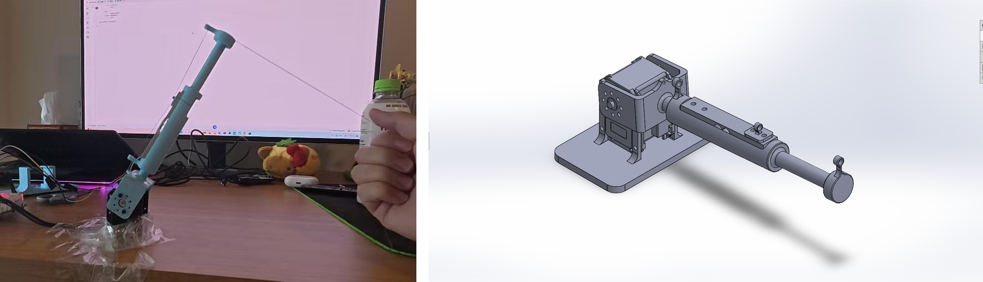
The resultant platform is a 1-DOF robotic fishing system that controls line tension following the hook-set phase. The robot employs sensor-based feedback control to manage tension regulation and disturbance rejection. Tension in the fishing line is detected by a load sensor, and the robot controls rod pitch angle based on the error of the detected tension. The control system logic was modeled and solidified in simulation as a tethered robot in which the fish-like load is an external disturbance via the line.
II. Control Objectives
Framed as an engineering problem, fishing can be characterized by three discrete modes: fish discovery (pre hook-set), tension regulation (post hook-set), and reeling.
Fish discovery describes the phase in which the fishing line is ‘cold’ and waiting for a fish to bite. The controller looks for a disturbance signal to indicate fish interest. A jigging action that mimics live bait may be used in this phase to increase fish hooking probability. This phase also includes holes/gaps in tension sensing caused by a fish already hooked that escapes the jurisdiction of the control domain. Algorithms and action routines may be employed to restore control over the fish.
Tension regulation is the project’s primary control objective, and centers on maintaining tension through the fishing line. The general control structure involves a physical load sensor that approximates the force through the line, and control algorithms that take this information to modulate the tension estimation data. Tension accommodation lends itself naturally to admittance control or some form of force regulation methodology, both of which became the primary control methods of exploration. Key concepts and considerations include tension regulation, virtual mass-spring-damper (MSD) admittance loops, and handling of highly stochastic loads.
Reeling may be added to successfully bring the fish to the desired endpoint. Reeling requires additional hardware to pull the string inward, which would complicate the load sensing packaging and add the mechanical complexity that comes with a reeling system. This system was not heavily pursued in this research, leaving it an avenue of future development.
III. Methods
Hardware
Mathematical Formulation
System definitions. The robotic fishing platform is modeled as a spherical manipulator. Although the control problem addressed in this work is restricted to the single pitch degree of freedom, the kinematics are derived for the general 2-DOF case so that the formulation extends directly to the planarized system discussed in future work.
- $q_1$: yaw angle of the base around the global $Z$-axis
- $q_2$: pitch angle of the rod relative to the horizontal $XY$ plane
- $L$: fixed length of the fishing rod from the pitch joint to the tip
- $h$: vertical height offset of the pitch joint from the ground
Forward kinematics. The forward kinematics map the joint space $(q_1, q_2)$ to the Cartesian task space $(x, y, z)$ of the rod tip. Projecting the rod length onto the horizontal plane gives the radial distance $r = L\cos(q_2)$. Decomposing this radial distance and accounting for the base height yields:
\[\begin{aligned} x &= L \cos(q_1)\cos(q_2) \\ y &= L \sin(q_1)\cos(q_2) \\ z &= h + L \sin(q_2) \end{aligned}\]Inverse kinematics. The yaw angle $q_1$ is isolated by taking the ratio of the $y$ and $x$ position equations. The two-argument arctangent is used to ensure the correct quadrant is selected. The pitch angle $q_2$ is found by relating the vertical displacement of the rod tip to the horizontal radial distance from the base:
\[q_1 = \operatorname{atan2}(y,\, x), \qquad q_2 = \operatorname{atan2}\!\left(z - h,\ \sqrt{x^2 + y^2}\right)\]Analytical Jacobian. The Jacobian is required for force control and admittance loops. It relates joint velocities to end-effector velocities, and maps external Cartesian forces back to joint torques via $\tau = J^{T} F_{\text{ext}}$. It is derived by computing the partial derivatives of the forward kinematic position equations with respect to $q_1$ and $q_2$:
\[J = \begin{bmatrix} \frac{\partial x}{\partial q_1} & \frac{\partial x}{\partial q_2} \\[4pt] \frac{\partial y}{\partial q_1} & \frac{\partial y}{\partial q_2} \\[4pt] \frac{\partial z}{\partial q_1} & \frac{\partial z}{\partial q_2} \end{bmatrix} = \begin{bmatrix} -L\sin(q_1)\cos(q_2) & -L\cos(q_1)\sin(q_2) \\ L\cos(q_1)\cos(q_2) & -L\sin(q_1)\sin(q_2) \\ 0 & L\cos(q_2) \end{bmatrix}\]This mapping is what allows a scalar line-tension measurement to be converted into a joint-space command in the admittance loop.
Codebase and Simulation
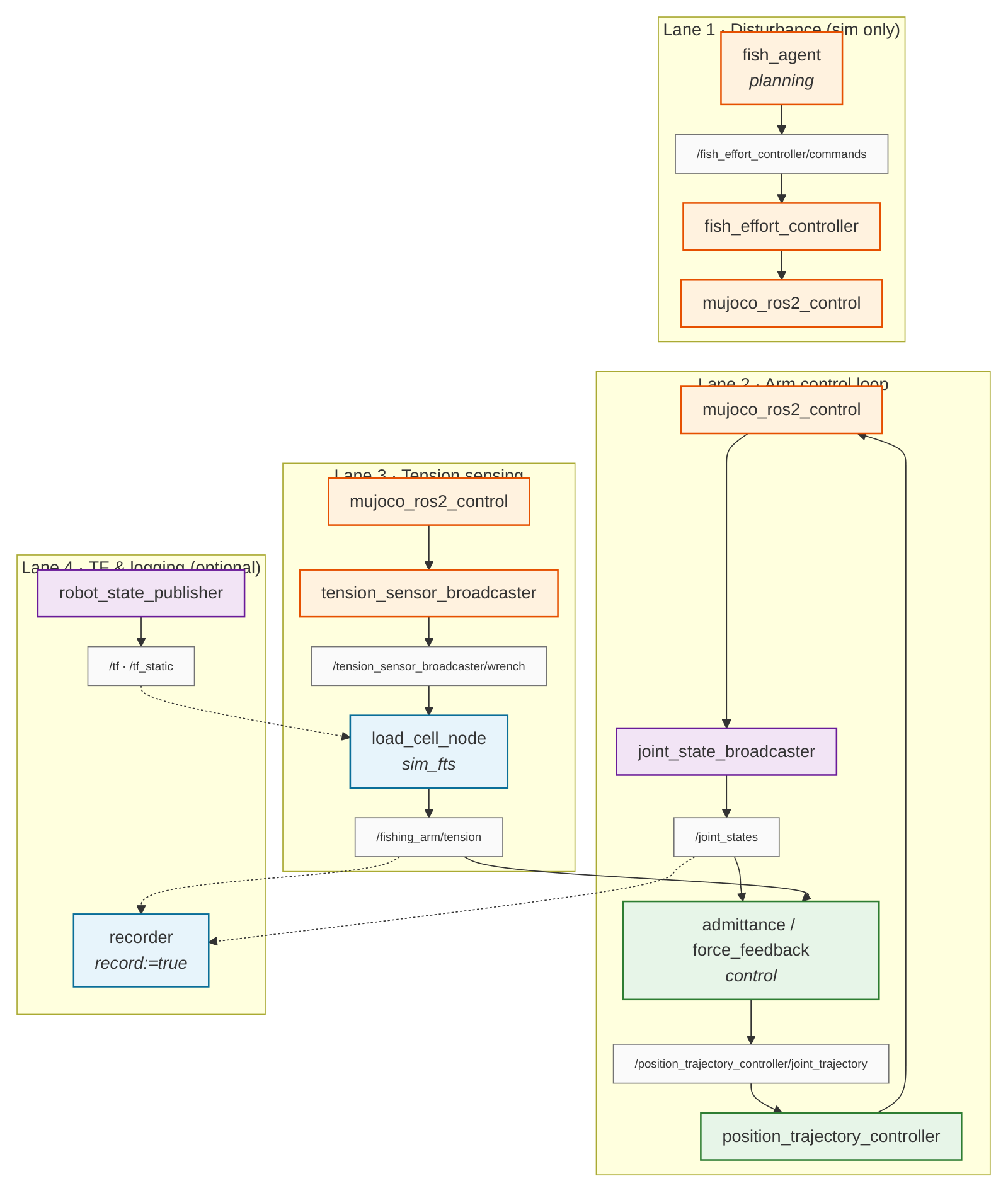
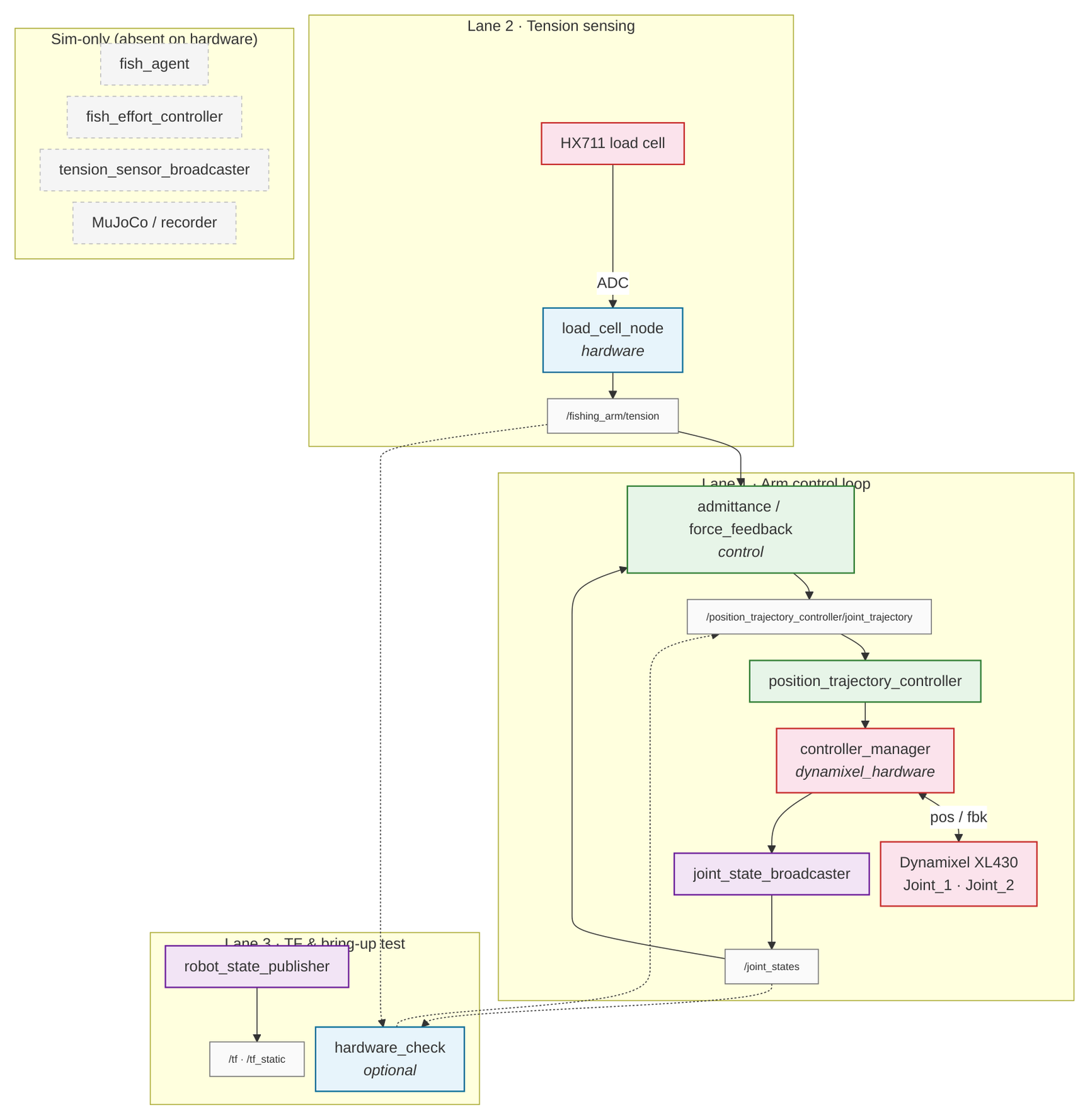
The ROS2 codebase was built so that the control logic interacts seamlessly with both MuJoCo simulation and hardware control. Additional documentation is available at the fishing bot code documentation.
| Package | Description |
|---|---|
bringup |
Launch configuration. Can launch simulation or hardware control based on preference. |
description |
Mesh and model descriptors. |
control |
Tension control package. |
planning |
Used to control randomness of ‘fish’ behavior. Can be thought of as a fish agent (the disturbance). |
sensors |
Sensor readings and publishing. |
interfaces |
Develops protocol for inter-node communication. |
diagnostics |
Recording and bring-up tests. |
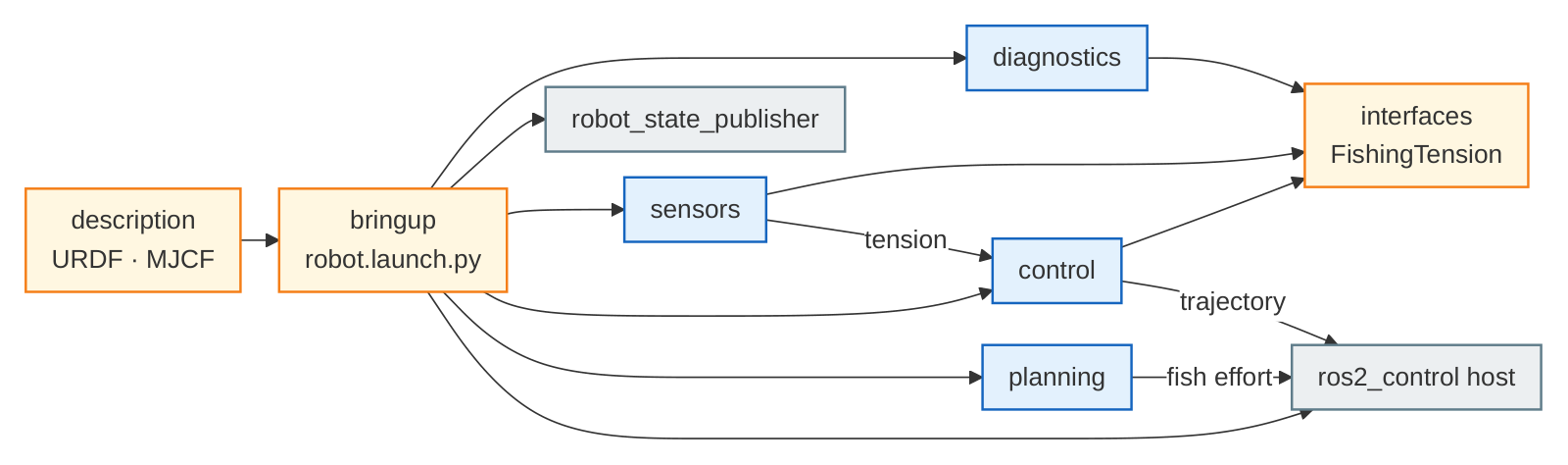

Simulation pipeline. The behavior of the fish is simulated as a repeatable disturbance for controlled testing, allowing the controllers to be evaluated reproducibly against a ROS2 control structure and MuJoCo backend.

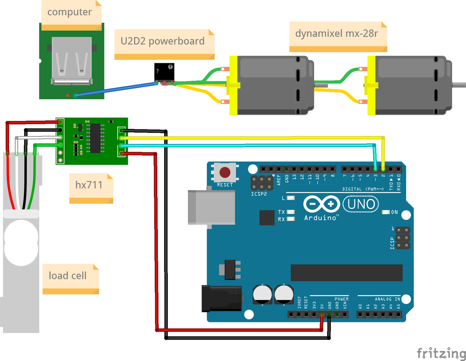
Hardware control pipeline. The hardware control flow path varies slightly from the simulation pipeline: the fish_agent disturbance and the MuJoCo-backed sensor broadcaster are replaced by the physical HX711 load cell and the Dynamixel hardware interface.

Control Architecture
Two controllers were developed and compared. Both share the same outer objective — convert a tension error into a rod pitch command — but differ in how that conversion is shaped.
Proportional Force Controller
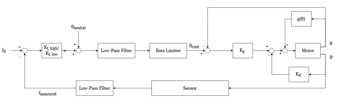
The proportional force controller directly regulates line tension by multiplying the tension error measured by the load cell by an asymmetric gain to brute-force a position command. An inner PD controller then tracks the position of the motor, and a gravity compensation term is injected into the motor command. Tension error is measured as the difference between desired and measured tension:
\[e_f = f_d - f_{\text{measured}}\]An asymmetric, state-dependent gain maps the force error to a corresponding position offset. When tension is too high the controller applies $K_{f,\text{high}}$; when tension is too low it applies $K_{f,\text{low}}$, with
\[K_{f,\text{high}} < K_{f,\text{low}}\]so that the rod ‘pulls’ harder when tension is low in order to pick up the slack of the line. Since the fish is hypothetically faster than the motor, the motor has to aggressively compensate for a lack of tension. When tension is too high, however, the gain is lower to prevent the robot from slamming forwards to yield to the fish, which would cause the line to immediately go slack. The gains are tuned to balance the rod being too stiff and unyielding (low $K$) against too soft, pliant, or over-reactive (high $K$).
The inner loop is a proportional-derivative controller that calculates the effort required to move the motor to the commanded position:
\[\tau = K_p(\theta_{\text{cmd}} - \theta) - K_d \dot{\theta} + g(\theta)\]Here $K_p(\theta_{\text{cmd}} - \theta)$ acts as a spring moving the motor toward the command position, $K_d$ dictates how aggressively the controller reacts to rate of change and acts as a brake, and the gravity compensation term $g(\theta)$ counteracts the downward pull of gravity. Low-pass filters and rate limiters are additionally used to prevent high spikes in current and to reject extraneous noise or high-frequency actions.
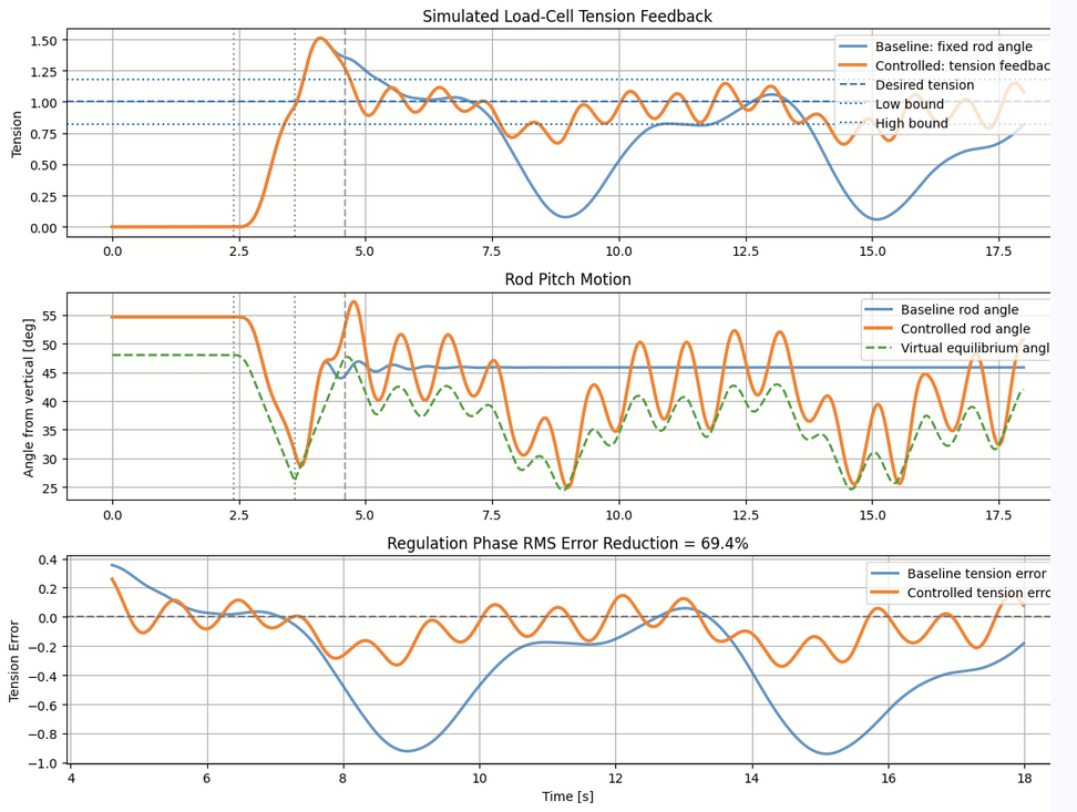
MuJoCo simulation results with $K_{f,\text{high}} = 160$ and $K_{f,\text{low}} = 400$ show the controlled line remaining close to the 1.0 N desired target, with a 69.4% RMS error reduction. However, there is constant chatter in the rod’s motion. This is concerning, since the motor is constantly reversing directions and the system indicates poor high-frequency rejection or smoothing even despite the filtering. Because of the system’s simplicity and high error reduction, this is the controller chosen for the initial hardware implementation.
Admittance Controller
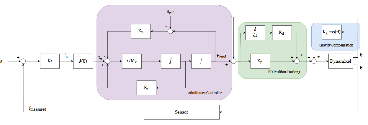
The admittance controller regulates line tension by simulating a virtual mass-spring-damper system, translating measured force errors into a dynamic position command. The target angle $\theta_{\text{cmd}}$ is governed by reacting to the tension error $e_f$ through the virtual physics equation:
\[M_v \ddot{\theta}_{\text{cmd}} + B_v \dot{\theta}_{\text{cmd}} + K_v(\theta_{\text{cmd}} - \theta_{\text{ref}}) = -J(\theta)\, k_f\, e_f\]Instead of relying on state-dependent asymmetric gains to manage slack, this architecture relies on sculpting these “virtual physics.” The force sensitivity gain $k_f$ scales the measured tension error and converts it into a virtual torque using the Jacobian $J(\theta)$. This torque acts upon a virtual mass $M_v$, which dictates the inertial resistance of the rod and naturally filters out high-frequency sensor noise. To prevent the rod from oscillating wildly or yielding too quickly, virtual damping $B_v$ acts as a physical shock absorber. Finally, virtual stiffness $K_v$ acts as a backbone, providing a restoring force that pulls the rod back to its neutral fighting angle $\theta_{\text{ref}}$ to prevent the pitch from drifting when the line goes slack. These parameters are tuned to balance a fast, responsive yield against dangerous phase lag or a slow, overly-stiff system.
The inner loop is again a PD controller, now tracking the simulated command position rather than a directly computed one:
\[\tau = K_p(\theta_{\text{cmd}} - \theta) + K_d \frac{d}{dt}(\theta_{\text{cmd}} - \theta) + K_g \cos(\theta)\]Because the virtual mass and damping mathematically restrict how fast the command signal can accelerate, the system naturally rejects extraneous noise and high-frequency actions without the need for artificial low-pass filters or strict rate limiters — a structural advantage over the proportional design, which requires them explicitly.
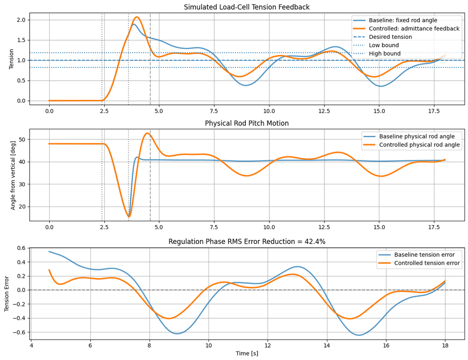
In simulation the controlled line yields gracefully to the tension spike, with a 42.4% RMS error reduction. While the numerical error reduction is lower than the proportional controller due to the inherent phase lag required to accelerate the virtual mass, the rod’s motion is exceptionally smooth and continuous. This is highly advantageous for hardware longevity, as it completely eliminates the jagged, high-frequency motor chatter and constant direction reversals seen in the proportional approach. The tradeoff is a more complex implementation and tuning process.
IV. Results
Engagement and Safety Logic
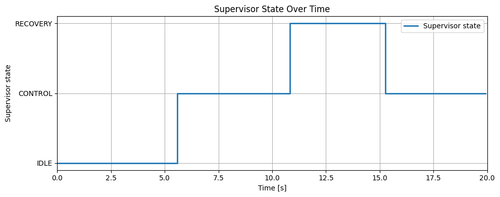
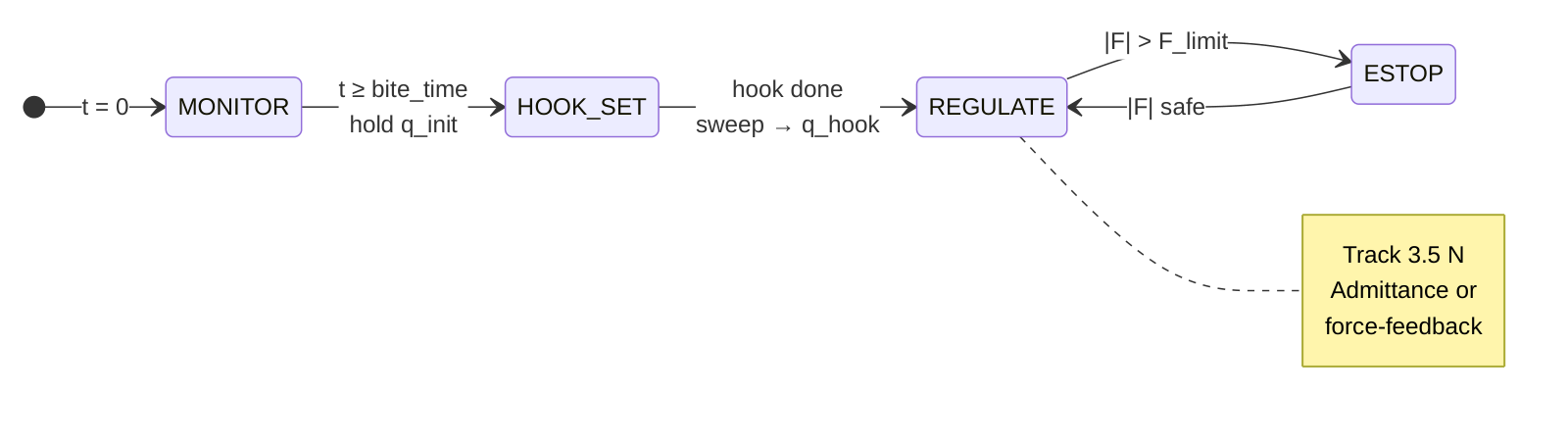
The engagement supervisor was evaluated during the hardware trial. Before line tension reached the bite-trigger condition, the controller remained in the IDLE state and commanded zero PWM, preventing the motor from responding to sensor noise or small disturbances. In this implementation the controller was activated only when measured tension exceeded 0.8 N for 0.10 s, representing the initial pulling event after a fish is hooked.
During active control, a low-tension condition was detected when measured tension stayed below 1.0 N. If this condition lasted more than 1.8 s, the supervisor entered the RECOVERY state to avoid continuously pulling against a slack line. Once measured tension recovered above 2.0 N, the controller returned to active control. The supervisor state plot shows this sequence, with transitions from IDLE to CONTROL, then to RECOVERY, and finally back to CONTROL after tension recovered.
Dynamic Controller Response
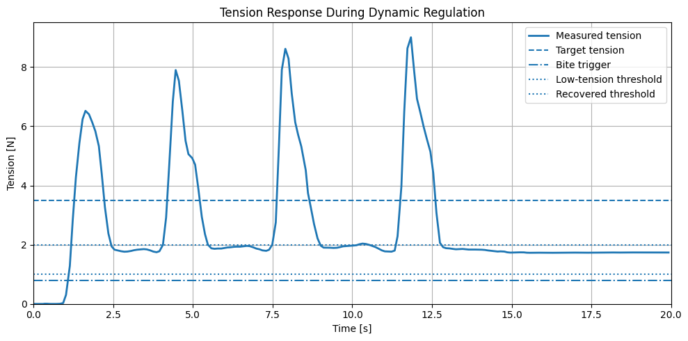
The dynamic controller response was evaluated using a trial with larger variations in applied line tension. Since the line was pulled manually, the sharp peaks in the tension curve should not be interpreted as a standardized disturbance input; the tension signal also depends on pulling speed, pulling direction, line slack, and the contact condition of the load cell. Figure 15 is therefore used to show the feedback signal received by the controller during a more dynamic pulling condition, rather than to evaluate the tension curve alone.
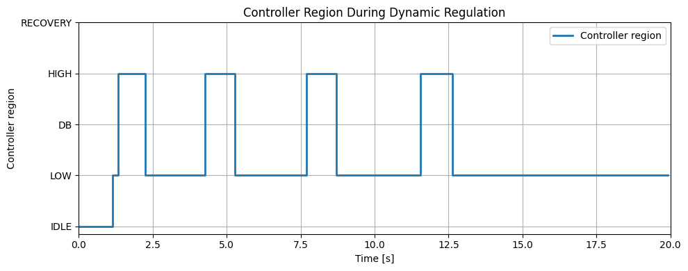
The controller response to these tension changes is shown more clearly in Figure 16. During the trial the controller compares measured tension with the target tension and the deadband, then selects the corresponding control region. When tension rises above the desired range the controller switches to the HIGH region, corresponding to a release action to reduce excessive line tension. When tension drops below the desired range the controller returns to the LOW region, where the motor pulls back to recover line tension. The repeated LOW/HIGH transitions show that the controller is actively responding to the sign of the tension error rather than applying a fixed motor command.
The LOW and HIGH regions should be interpreted as two operating regions of the same tension-regulation controller, rather than two separate controllers for reeling in and letting out the line. The controller switches its response direction based on the sign of the tension error, while still using one overall feedback-control structure.
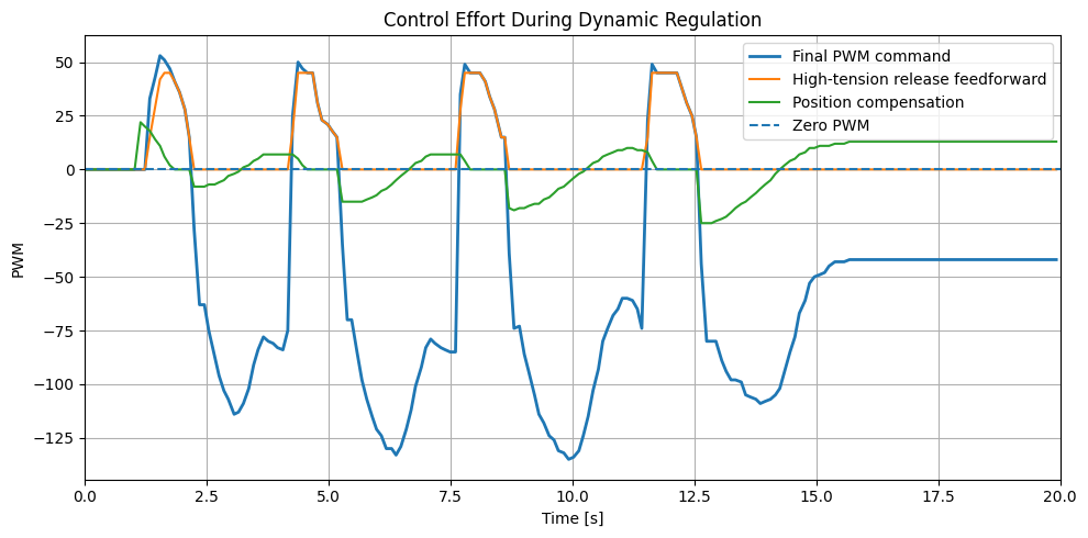
Figure 17 shows how these feedback decisions are converted into actuator commands. The final PWM command sent to the Dynamixel motor is shown alongside two major contributing terms: the high-tension release feedforward and the position compensation term. The zero-PWM line separates the two actuation directions — positive PWM commands are associated with release actions during high-tension events, while negative PWM commands are associated with pull-back corrections when tension becomes too low.
The positive PWM pulses appear when the controller enters the HIGH region, showing that the controller is actively trying to release the rod and reduce excessive tension. After tension decreases, the final PWM command becomes negative, corresponding to the LOW-region pull-back action. The position compensation term changes more slowly because it depends mainly on rod position rather than the instantaneous tension peak. The final PWM command is thus the combined output of tension-based correction and position-based compensation.
The PWM command appears relatively step-like because the prototype was implemented using PWM mode on the Dynamixel motor rather than a calibrated torque or current-control mode. In addition, the controller uses deadband-based switching logic, so control effort changes more noticeably when measured tension moves between the LOW, deadband, and HIGH regions. The PWM signal should therefore not be interpreted as an ideal continuous torque command; it shows the direction and relative strength of the motor response produced by the tension-regulation logic.
The asymmetry between positive and negative PWM commands is intentional. During release, the goal is to reduce excessive tension without moving the rod forward too aggressively — a very aggressive release could either drive the rod close to the forward limit or reduce line tension too quickly and create slack. During pull-back, however, the motor needs more authority to rebuild line tension while overcoming gravity, friction, and mechanical resistance. This is why the negative pull-back commands are larger in magnitude than the positive release commands.
Taken together, Figures 15–17 show the intended closed-loop behavior: Figure 15 provides the measured tension feedback, Figure 16 shows the corresponding HIGH/LOW region selection based on tension error, and Figure 17 shows the motor command generated from this feedback logic. The robot actively responds to changes in line tension by switching control modes and commanding the actuator in the expected direction.
For an actual fishing application, large force oscillations would not be desirable, as they could increase the risk of excessive line loading or temporary loss of line tension. Here the rapid-pull trial was mainly used as a stress test to check whether the controller could detect sudden tension changes and respond in the correct direction. The results show the expected switching behavior, but also suggest that smoother mode transitions and improved inner-loop actuation would reduce oscillations in future versions.
Post-Transient Regulation Performance
The post-transient regulation trial evaluated the controller under a more sustained pulling condition after initial engagement. An initial manual pull was applied to create a large tension deviation, and the line was then held as steadily as possible. Although the input was still applied by hand and should not be treated as a standardized step input, this trial better represents controller behavior after the large initial disturbance has passed.
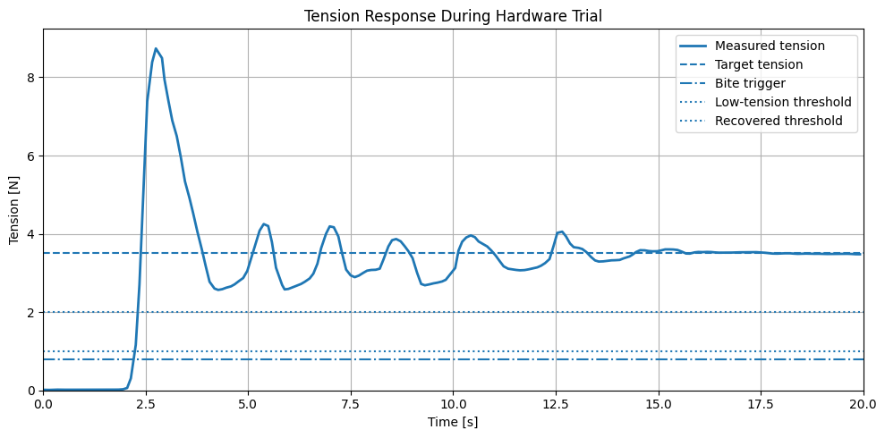
The target tension was set to 3.5 N. During the initial engagement phase the measured tension contains a large transient peak, caused mainly by initial line engagement and manual pulling input. After this transient and the following correction motions, the controller brings measured tension back toward the target range and holds it near the desired value.
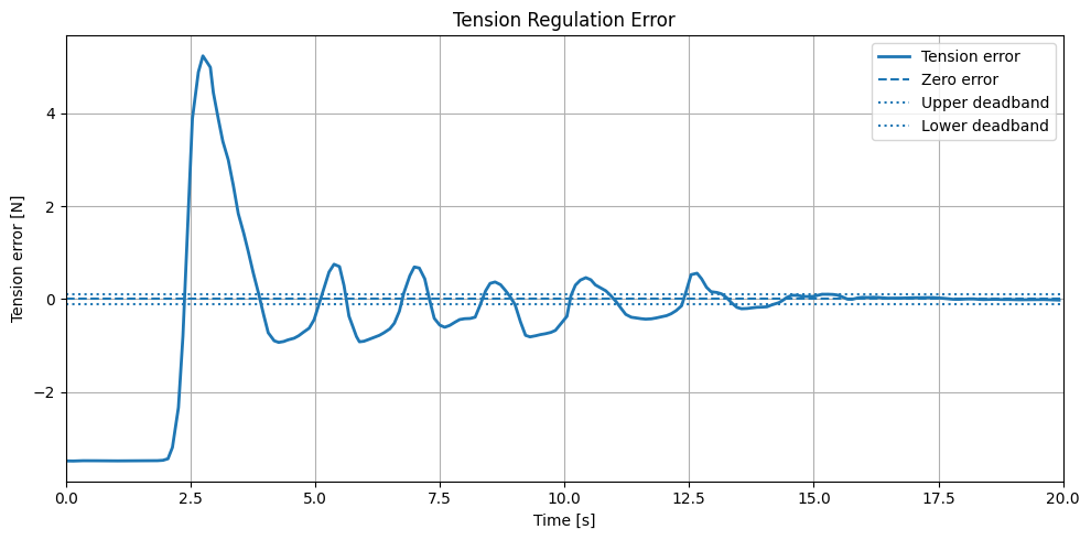
Rather than treating the full response as a standard settling-time test, the final portion of the trial was used as a post-transient evaluation window. Over this window:
| Metric | Value | % of target |
|---|---|---|
| Target tension | 3.50 N | — |
| Mean measured tension | 3.52 N | — |
| Mean absolute error | 0.025 N | 0.72% |
| RMSE | 0.036 N | 1.03% |
Once the large transient response had passed, the controller regulated line tension with a small remaining error.
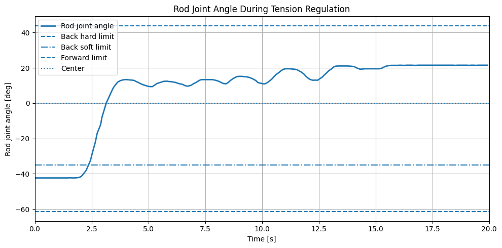
Figure 20 shows the rod joint angle during the same trial, in degrees, providing additional context for the regulation behavior. During the initial engagement and correction phase, tension error is relatively large and the actuator changes rod angle to establish line tension and reduce the error. As measured tension approaches the target, tension error becomes smaller and the rod joint angle remains near a stable operating posture, indicating that actuator adjustment is consistent with the reduction of tension error. The joint angle is not expected to match tension error exactly, since measured tension also depends on manual pulling input, line slack, load-cell contact, and friction. Figure 20 therefore shows actuator motion and final rod posture, while Figure 19 remains the main performance metric for tension regulation.
V. Current Challenges
Although hardware testing shows that the controller can regulate line tension, the current setup has several practical limitations.
Non-standardized disturbance. External line tension was applied by hand during experiments rather than generated by a standardized disturbance source. This made the test closer to an actual fishing interaction, but it also means the measured tension curve is affected by pulling speed, pulling direction, and line slack. Some sharp peaks and sudden drops in the tension signal should be interpreted as part of the manual interaction with the line rather than attributed to the controller alone. The hardware results are therefore used to demonstrate controller behavior under realistic manual interaction, not as a standardized disturbance-response benchmark.
Indirect actuator-to-sensor relationship. Unlike a pure position-control task, where motor angle can be measured and controlled directly, line tension depends on several physical factors between actuator and sensor. Line slack, fishing-line compliance, load-cell contact condition, and mechanism friction can all affect measured tension even when the motor command is the same. As a result, small motor motions do not always produce an immediate or proportional change in tension.
PWM-based actuation. Since the motor is commanded through PWM rather than a precise torque or position controller, small corrective commands may need to overcome static friction, gravity, and mechanical resistance before visible rod motion occurs, making the actuator response less smooth during fine tension corrections. The tension regulation result should be understood as the combined behavior of controller, motor actuation, fishing line, and load-cell measurement, rather than a direct one-to-one mapping between joint angle and tension.
VI. Future Work
Upon further understanding of the problem, it became clear that this apparently simple tension management task has incredibly deep and rich control ideas embedded beneath the surface. This led to a deep dive into potential control tools that may bolster the robustness of the control system.
Algorithms
Higher-dimensional sensing and hybrid control. Taking the 1-DOF control problem to the more realistic 2-DOF planarized case introduces nonlinear coupling dynamics and orthogonal subspaces. Less obvious is the added complication regarding sensing capability. Given a limited 1D load sensing framework, sensor fusion and interpretation techniques are required to ensure optimal tension estimation in the higher-dimensional space. Instead of a direct linear force/tension estimation relation, a more precise tension vector is needed to perform control feedback on. Using load sensor information together with kinematic state via encoders, kinematic variation/dithering may be employed to back out the tension vector estimate. If joint torques are also used, a sensor fusion technique such as an extended Kalman filter may be necessary. Hybrid control may then come into play, allowing admittance in the tension-management force-adaptive axis and rigid positional control in perpendicular axes.
Robust state switching. Discrete states are naturally embedded within the fishing control problem, which makes it control-rich. The transition from fish searching to hook set, or from having a fish to losing tension, are both examples of discrete switching behavior. The current FSM implementation uses basic force thresholding that induces highly volatile “chatter” — rapid, unstable, and unnecessary state switching. Several stability insurance techniques could augment the FSM:
- Hysteresis better characterizes switching conditions by enforcing anisotropic force thresholds for entering and exiting a state.
- Debouncing adds time-based thresholding to limit false or rapid triggering.
- Smoothing filters at transition points help initiate bumpless transfer and eliminate unwanted transient spikes in control effort.
- Tension break detection (rate of force change) with accompanying funnel synthesis bounds tracking error behavior. Funnel synthesis drops the controller into a safe, heavily damped recovery ‘funnel’ in case of line break, preventing the arm from violently whipping backward and breaking motors. The same concept can be applied for control regain.
- Gain scheduling customizes dynamic behaviors specific to each state’s concerns when admittance control is in use.
Learning-based augmentation. The control loop could be augmented with an adaptive neural network feedforward term that learns the stochastic frequency of the fish’s pulling behavior, effectively predicting the required $q_d$ before tension error grows too large. The preexisting sim-real framework can also be set up as a sim-to-real training pipeline, using simulation as an AI training tool to optimize tensioning behavior on the real robot. This can be achieved either by using direct RL methods to build a neural-based controller, or by employing layered RL to tune controller parameters of a pre-designed control framework. The simulation pipeline can also simply be used for adaptive control tuning without AI.
Noise Reduction and Filtering
To properly target fish in an unpredictable open ocean scenario, probabilistic state estimation (HMM, Bayesian filtering) may be required. This is often important in partial observability and limited information scenarios such as real-world RL training cases. Frequency and derivative of the force may be used to distinguish between fake disturbances (boat rocking, snag on seaweed) and an actual fish. However, if the operating environment has no partial observability or obstruction concerns, the problem that state estimation seeks to solve may simply be bypassed by using computer vision to distinguish between a fish and ignorable entities.
Hardware
Redundantly actuated serial joint. This augmentation was initially inspired by a desire to emulate rod compliance with active control capability, but the larger control picture is a macro-micro manipulator structure. The lower heavy base joint handles low-frequency, high-amplitude positioning (such as tracking a boat’s movement), while a smaller, redundantly actuated serial joint near the tip can be tuned with a much higher control loop frequency to handle high-frequency stochastic disturbances. The benefit is inertial decoupling: improved torque efficiency, as jerky movements are handled by the actuator near the tip and do not cause the heavy base motor downstream to respond unnecessarily and move high inertial loads.
The added joint also opens the possibility of null space optimization with the introduction of infinite joint configurations, allowing secondary optimization objectives besides tension management, such as torque minimization. The secondary joint can also be treated as a dynamic impedance shaping element, with the redundant motor acting as a dynamically tunable physical stiffness unit that adheres to control needs.
Passive structures. A compliant segment added to the end of the rod can act as a mechanical low-pass filter, dealing with incredibly jerky fish motion in true fishing scenarios as well as improving bumpless transfer stabilization during state transitions to reduce risky torque spikes.
Improved test rig. An actuatable object mimicking a fish, with planarized movement capabilities, would allow varied and repeatable experiments on the hardware system and its accompanying controller design.
Practical Additions
Other considerations that would bring the automated fishing system closer to a market-available product include an actuated hooking system and a tensioning reel mechanism. Each comes with its own host of hardware implementation and control framework problems.
Appendix: Bill of Materials
| # | Component | Qty | Description |
|---|---|---|---|
| 1 | Arduino Uno R3 | 1 | Sensor reading and hardware communication |
| 2 | HX711 | 1 | Load-cell signal conditioning module |
| 3 | Load Cell | 1 | Measures fishing-line tension |
| 4 | Dynamixel MX-28R | 2 | Smart servo motors for rod actuation |
| 5 | U2D2 | 1 | USB-to-Dynamixel communication adapter |
| 6 | 12 V DC Power Supply | 1 | Powers the Dynamixel motors |
| 7 | USB Cable (A–B) | 1 | Arduino-to-computer connection |
| 8 | Dynamixel TTL Cable | 2 | Daisy-chain communication between servos |
| 9 | Jumper Wire Set | 1 set | Connections between Arduino, HX711, and load cell |
| 10 | Fishing Rod Assembly | 1 | Custom 1-DOF rod structure |
| 11 | M2 Screws | 10 | Connect motor to 3D-printed assembly |
References
Nathan Ge
Department of Mechanical and Aerospace Engineering
University of California, Los Angeles
Email: nzge@g.ucla.edu
Acknowledgment
The authors thank Professor Veronica Santos for guidance and instruction throughout the MAE 263C Controls of Robotic Systems course. Their insights into robotic control formed the foundation of this project.
-
M. AlYaseen, O. Alajmi, N. Al-Attal, and A. Al-Saleh, “Autonomous Fishing Rod,” College of Engineering and Applied Sciences, American University of Kuwait, Kuwait, 2019. ↩ ↩2
-
J. Cook, “Robotic Fishing Pole Casts and Reels Automatically,” Hackster.io, 2019. [Online]. Available: https://www.hackster.io ↩ ↩2
-
Stanford CHARM Lab, “Haptic Fishing Robot,” Stanford University, 2024. [Online]. Available: https://charm.stanford.edu ↩ ↩2
-
G. Lai, S. Zhou, W. Yang, X. Wang, and F. Wang, “Prescribed fixed-time adaptive neural control for manipulators with uncertain dynamics and actuator failures,” Mathematics, vol. 11, no. 13, p. 2925, 2023. [Online]. Available: https://doi.org/10.3390/math11132925 ↩