
Hardware Design
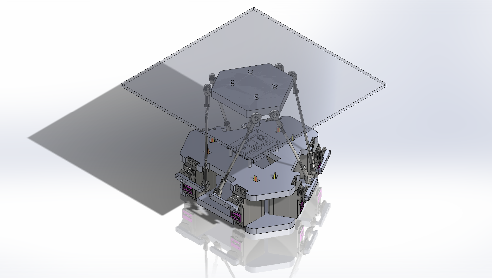
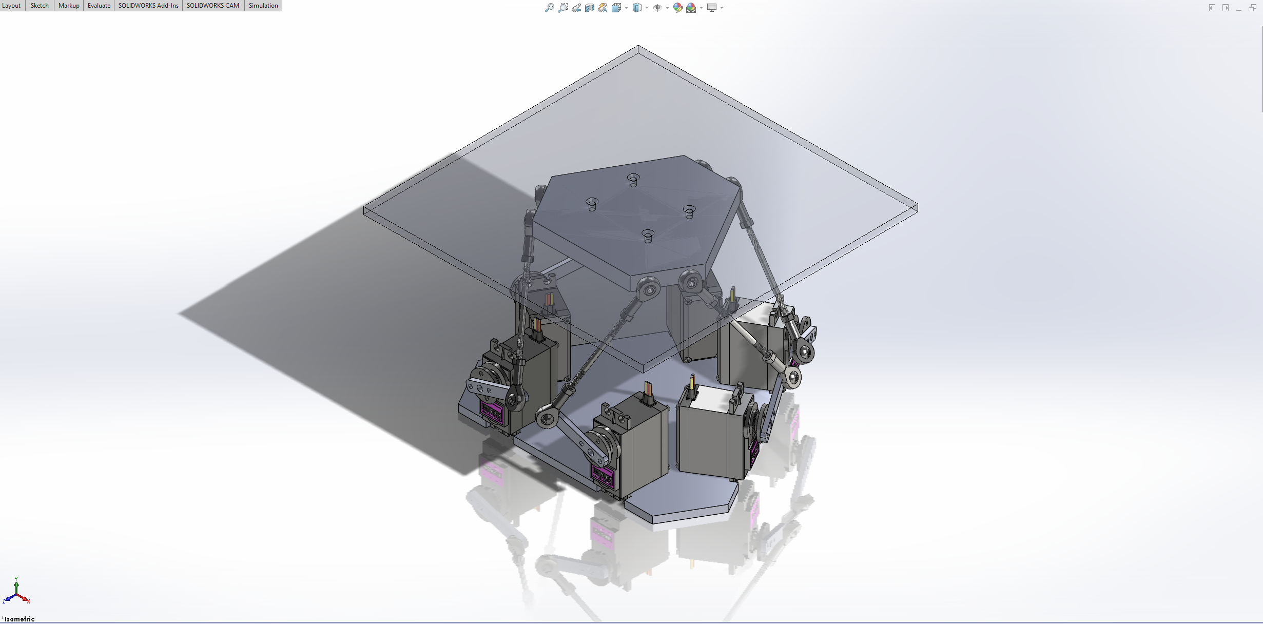
Model
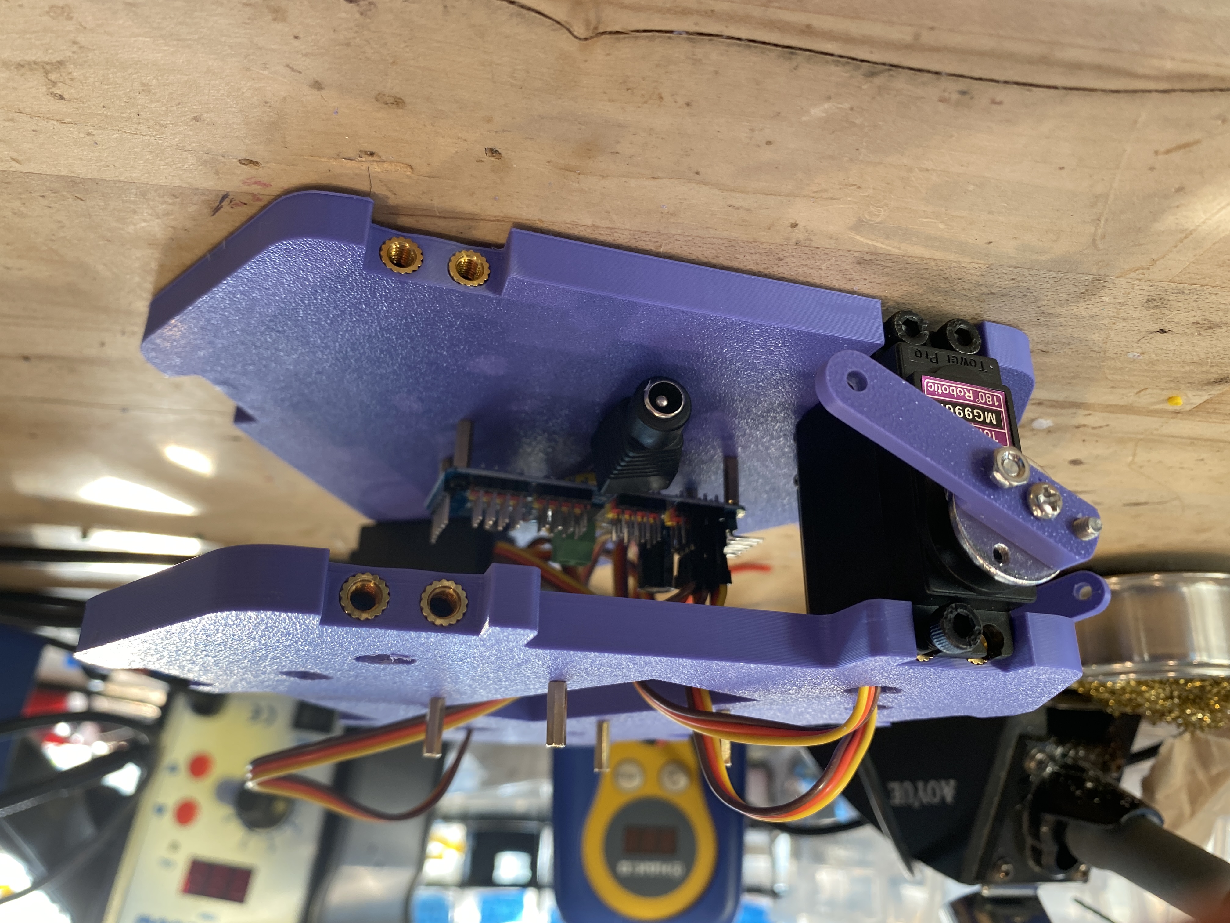
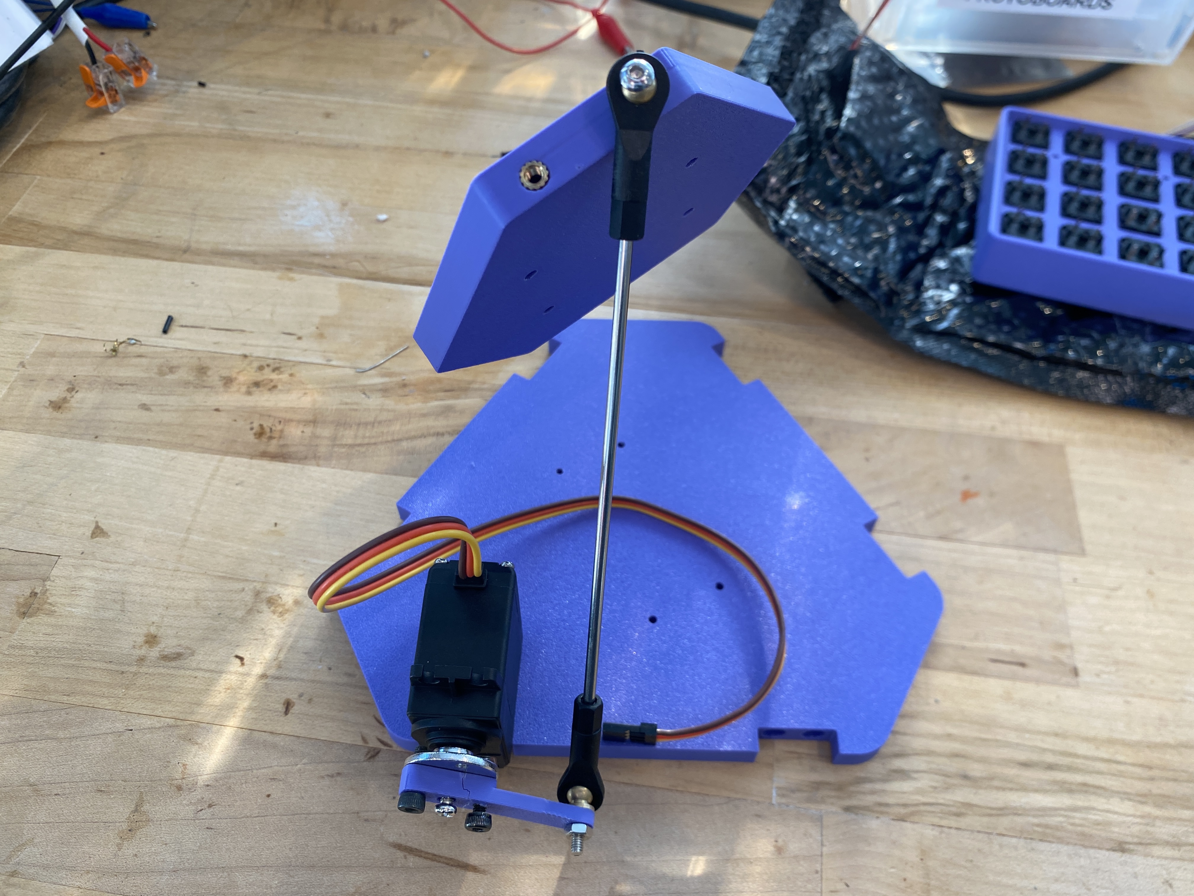
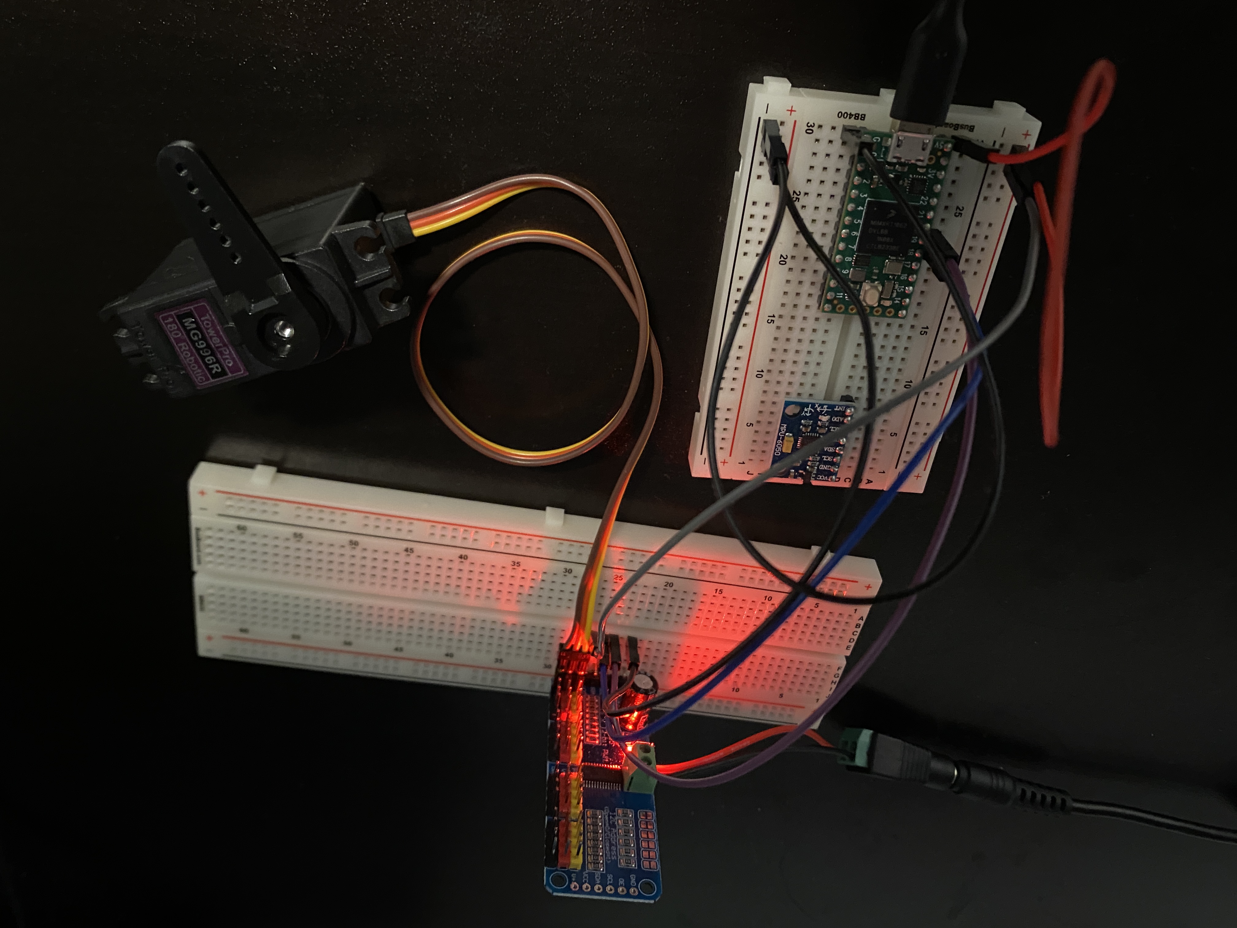
Components
Base plate Base plate cover Platform Top Plate
| Teensy + Raspberry Pi Pico | asdas |
| Proto Board | |
| 6V 10A Power Supply | |
| HiLetgo PCA9685 16 Channel 12-Bit PWM Servo Motor Driver | |
| MPU6050 |
| Tower MG996R 180 degree servo | asdas |
| 25T Servo Horn | |
| Servo Link | |
| 6 Shafts with threaded ball joint |
Schematic

Dimensions
Simple base, platform, and link proportion calculations formatted in a csv file through Jupyter notebook serve as global variables to parametrize CAD model.
![]()
Software Design
Servo Driver
#include "servos.h"

Servos::Servos() {
  pca9685 = Adafruit_PWMServoDriver();
  servo_count = NUM_SERVOS;
}

// Initialize the PCA9685
void Servos::init() {
  pca9685.begin();
  pca9685.setOscillatorFrequency(25000000);  // Set to 25 MHz (default)
  pca9685.setPWMFreq(PWM_FREQ);  // Set PWM frequency for servos (50Hz)
  delay(10);
}

// Set the PWM signal on the specified channel
void Servos::setServoAngle(uint8_t channel, uint16_t angle) {
  // Ensure angle is in valid range
  if (angle < MIN_SERVO_ANGLE) angle = MIN_SERVO_ANGLE;
  if (angle > MAX_SERVO_ANGLE) angle = MAX_SERVO_ANGLE;
  pca9685.setPWM(channel, 0, angleToPWM(angle));
}

void Servos::setServoAngles(uint16_t angles[]) {
  for (uint8_t i = 0; i < servo_count; i++) {
    setServoAngle(i, angles[i]);
  }
}
Inverse Kinematics
![]()
The inverse kinematic derivation is not incredibly complex, but not completely non-trivial. I won’t expound upon the derivation in exceptional detail here, as there are many online resources that present the derivation clearer that I am capable of. [^2] However, here is the general form of the angle derived from the inverse kinematic computation.
\[\begin{gathered} \alpha=\sin^{-1}{\frac{\mathrm{L}}{\sqrt{\mathrm{M}^{2}+\mathrm{N}^{2}}}}\cdot\tan^{-1}{\frac{\mathrm{N}}{\mathrm{M}}} \\ \mathrm{where}\\ \quad L=l^{2}-(s^{2}-a^{2}) \\ \mathrm{M}=2\mathrm{a}\left(z_{p}-z_{b}\right) \\ \mathrm{N}=2\mathrm{a}\left[\cos\beta\left(x_{p}-x_{b}\right)+\sin\beta\left(y_{p}-y_{b}\right)\right] \end{gathered}\]PID Control
I employed a simple positional control PID algorithm to stabilize the position of a ball placed on top of the platform
Web Interface
Next.js webserver hosted on Raspberry Pi 5 displays control interface. ROS backend integration takes keypresses, button presses, and mouse clicks and transforms it into commands that the Stewart platform can interpret.
ROS Integration
Travel router provides a contained subnetwork for wireless connection between host computer, raspberry pi webserver, and raspberry pico.
Micro-ROS Agent
Micro-ROS on Pico
Build Log
3-29-25: Refined CAD for printing
3-20-25: Refined CAD for printing
3-13-25: Refined CAD for printing
3-11-25: CAD prototype
3-6-25: Servo driver code is functional
References
Inspiration
3DOF STEWART PLATFORM: ECE4760 MICROCONTROLLERS FINAL PROJECT
Stewart Platform by thiagohersan
Ball Balancing Robot by Aaed Musa
6-DOF Stewart Platform by Yichuan Wang
Sources
[^1]: “Stewart Platform Control”, Accessed March 6, 2025.
[^2]: Robert Eisele. Inverse Kinematics of a Stewart Platform. Feb 2019. “Inverse Kinematics of a Stewart Platform”
[^3]: K. Ogata. Modern Control Engineering. Pearson, 2010.